
Vehicle HVAC system with combination heat exchanger for heating and cooling vehicle interior

一种热交换器、暖通空调的技术,应用在加热/冷却设备、车辆部件、照明和加热设备等方向

Active Publication Date: 2017-03-15
FORD GLOBAL TECH LLC
View PDF11 Cites 1 Cited by
  • Summary
  • Abstract
  • Description
  • Claims
  • Application Information

AI Technical Summary

Problems solved by technology

CO produced in the passenger compartment 2 release may result in the displacement of oxygen over a short period of time

Method used


Image

  • Vehicle HVAC system with combination heat exchanger for heating and cooling vehicle interior

Examples


Embodiment Construction

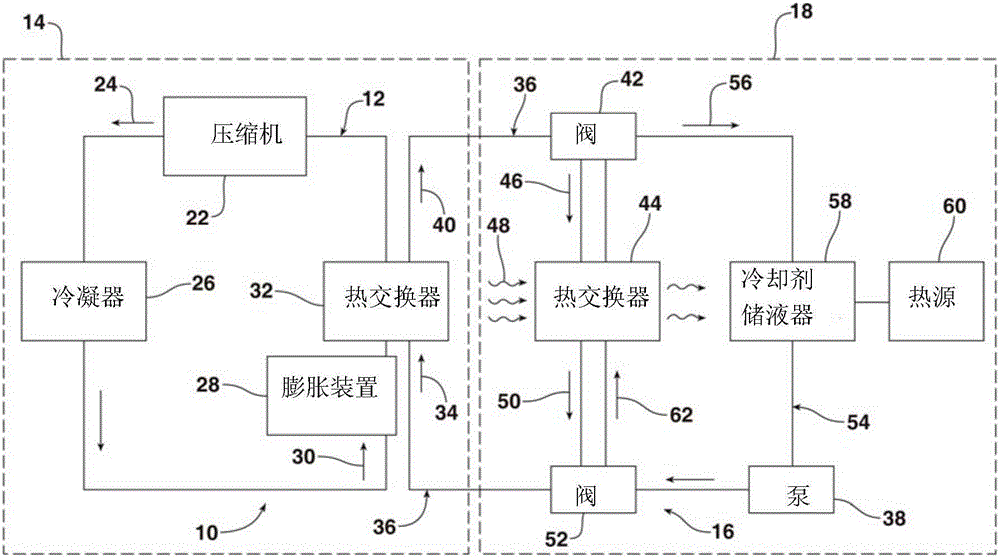
[0024] now refer to figure 1 , figure 1 A schematic diagram of a vehicle heating, ventilation and air conditioning (HVAC) system 10 including a high pressure CO positioned within the engine compartment 14 of the vehicle is shown. 2 A circuit 12 and a coolant circuit 16 positioned at least partially within a passenger compartment 18 for heating and cooling the passenger compartment via a ventilation device (not shown) positioned therein. CO 2 The circuit is completely contained within the engine compartment.

[0025] In the described example, CO 2 Circuit 12 includes a compressor 22 . In the A / C (air conditioning) mode of operation of the system 10, the compressor 22 compresses a fluid, which in the depicted embodiment is carbon dioxide (CO 2 )gas), thus increasing the CO 2 The pressure and temperature of the gas. High temperature, high pressure CO 2 Gas exits compressor 22 , as indicated by action arrow 24 , and flows into condenser 26 .

[0026] In summary, in the de...


PUM


Abstract

The invention provides a vehicle HVAC system with combination heat exchanger for heating and cooling vehicle interior. The vehicle having a heating, ventilation and air conditioning (HVAC) system for heating and cooling a passenger compartment is provided. The vehicle may be described as including a CO2 loop positioned within an engine compartment, a coolant loop positioned at least partially within the passenger compartment, a first heat exchanger positioned within the engine compartment for transferring heat from a coolant within the coolant loop to a CO2 within the CO2 loop, a pump for moving the coolant within the coolant loop, a second heat exchanger within the coolant loop for heating or cooling an air temperature within the passenger compartment, and first and second valves for controlling movement of the coolant through the second heat exchanger and a heated coolant loop.

Description

technical field [0001] This document relates generally to vehicle heating / cooling systems, and more particularly to a vehicle heating, ventilation and air conditioning system having an integrated heat exchanger for heating and cooling the interior of a vehicle. Background technique [0002] The use of auxiliary heating, ventilation and air conditioning (HVAC) systems in vehicles is well known. Such systems may include operating at high pressure in which CO 2 circuit. When positioned even partially within the passenger compartment of a vehicle, additional measures must be taken to protect the vehicle occupants from malfunctions related to the high voltage system. CO produced in the passenger compartment 2 release may result in the displacement of oxygen over a short period of time. Therefore, there is a need to eliminate the extra measures and concerns associated with such systems. [0003] This can be achieved by placing the CO 2 The circuit is accomplished by moving c...

Claims


Application Information

Patent Timeline
Patent Type & Authority Applications(China)
IPC IPC(8): B60H1/22B60H1/32
CPCB60H1/22B60H1/3204F25B41/34B60H1/00885B60H1/32281F25B9/008F25B25/005Y02B30/70B60H1/00B60H1/00328
Inventor 蒂姆·范·埃文斯曼弗雷德·科贝尔施泰因
Owner FORD GLOBAL TECH LLC
Features
  • Generate Ideas
  • Intellectual Property
  • Life Sciences
  • Materials
  • Tech Scout
  • Unparalleled Data Quality
  • Higher Quality Content
  • 60% Fewer Hallucinations
Learn More