Rainwater utilization system and urban road
A technology of rainwater and rainwater wells, applied in waterway systems, sewage removal, water supply devices, etc., can solve the problems of expanding the scale of drainage facilities, increasing the investment and cost of urban drainage facilities, increasing the load of urban drainage facilities, etc., to reduce the probability of use , reduce the scale, improve the effect of utilization
- Summary
- Abstract
- Description
- Claims
- Application Information
AI Technical Summary
Problems solved by technology
Method used
Image
Examples
no. 1 example
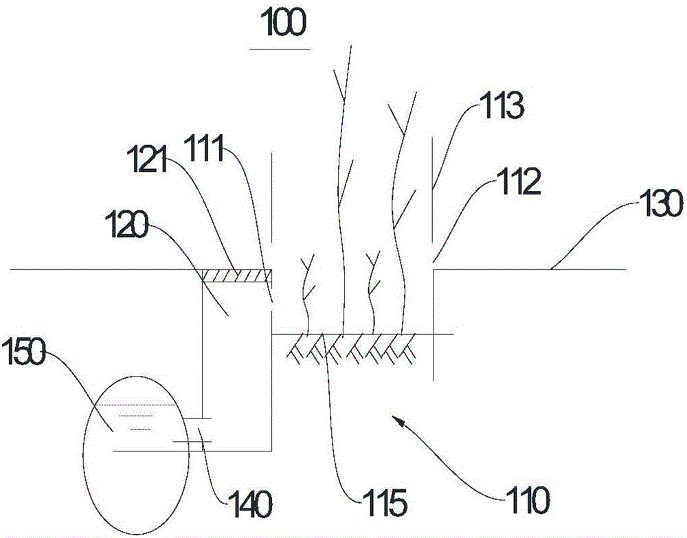
[0031] see figure 1 , this embodiment provides a rainwater utilization system 100 , which includes a sunken water absorption system 110 and a rainwater well 120 . The rainwater well 120 is disposed on one side of the concave water absorption system 110 and is located below the road surface 130 . The rainwater well 120 can make the water on the road surface 130 flow into the ground, and play a role in drainage and temporary storage of water.
[0032] Further, the top of the rainwater well 120 is provided with a rainwater well cover flush with the road surface 130 . The rainwater manhole cover is the first grid 121 . Rainwater can quickly pass through the first grille 121 without accumulating on the road surface 130 to form stagnant water. At the same time, the first grille 121 can also prevent excessively large waste from entering the rainwater well 120, causing blockage of the rainwater well 120, which is inconvenient to discharge rainwater. The first grille 121 can have a...
no. 2 example
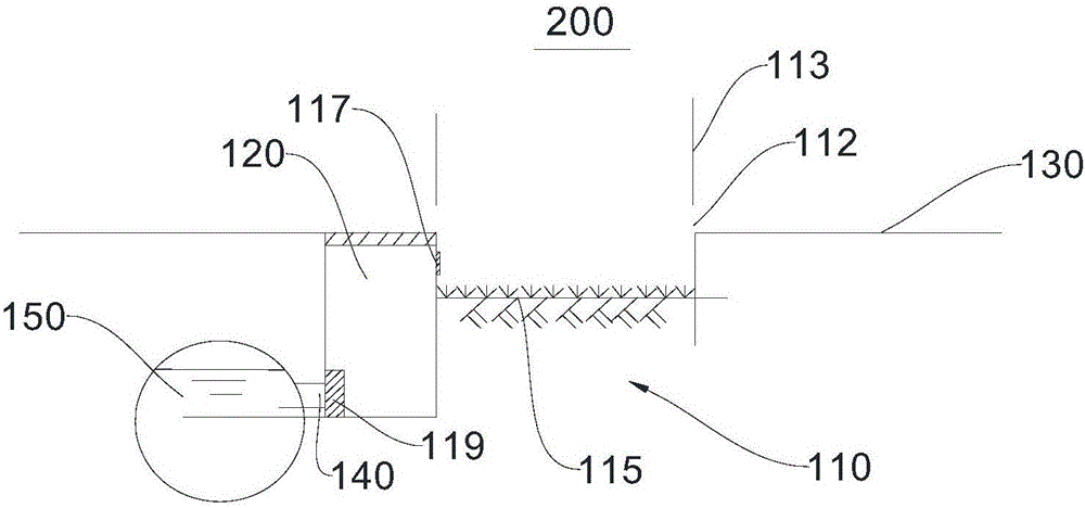
[0042] The structure of the rainwater utilization system 200 provided in this embodiment is substantially the same as that of the rainwater utilization system 100 in the first embodiment, the only difference being that the rainwater utilization system 200 of this embodiment adds a filter 119 and a second grill 117 .
[0043] see figure 2 , the height difference between the water absorption area 115 of the rainwater utilization system 200 and the road surface 130 is 30 cm. The water-absorbing area 115 is an isolation zone for planting lawns. The filter 119 is arranged at one end of the connecting pipe 140 communicating with the rainwater well 120 , and is flexibly connected with the rainwater well 120 . When rainwater enters the rainwater well 120 through the overflow port 111 or the first grille 121 , it will bring back some soil and garbage, which will easily cause the rainwater pipe 150 to be blocked after entering the rainwater pipe 150 . In turn, the rainwater cannot be...
no. 3 example
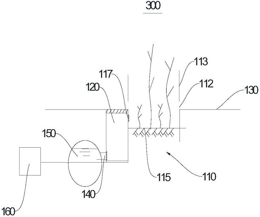
[0046] The rainwater utilization system 300 provided in this embodiment is based on the rainwater utilization system 200 in the second embodiment, and a lifting platform 114 , a lifting frame 116 and a water storage tank 160 are added.
[0047] see image 3 and Figure 4 , the height difference between the water absorption area 115 of the rainwater utilization system 300 and the road surface 130 is 40 cm. The height difference between the overflow port 111 and the water absorption area 115 is 30 cm. Lifting platform 114 and lifting frame 116 are all located in rainwater well 120, meanwhile, the bottom of lifting frame 116 is fixedly connected with the bottom of rainwater well 120, and the top of lifting frame 116 is fixedly connected with lifting platform 114. When the rainwater well 120 is a cuboid, the length and width of the lifting platform 114 are consistent with the length and width of the rainwater well 120 . When the rainwater well 120 is a cylinder, the diameter of...
PUM
 Abstract
Description
Claims
Application Information
 - R&D
- Intellectual Property
- Life Sciences
- Materials
- Tech Scout
- Unparalleled Data Quality
- Higher Quality Content
- 60% Fewer Hallucinations
Browse by: Latest US Patents, China's latest patents, Technical Efficacy Thesaurus, Application Domain, Technology Topic, Popular Technical Reports.
© 2025 PatSnap. All rights reserved.Legal|Privacy policy|Modern Slavery Act Transparency Statement|Sitemap|About US| Contact US: help@patsnap.com


