
Deposited carbon regeneration and thermal fatigue simulation testing system of diesel fuel particulate trap

A particle trap and simulation testing technology, which is applied in the testing of machine/structural components, testing of mechanical components, instruments, etc., can solve the problem that the engine bench cannot be developed and tested by DPF, and the cost of the engine test bench is high. Engine development Time cycle and other issues, to achieve the effect of simplifying user testing process and reducing system investment cost

Inactive Publication Date: 2017-03-15
SHANGHAI WAYEMER TECH CO LTD
View PDF6 Cites 9 Cited by
  • Summary
  • Abstract
  • Description
  • Claims
  • Application Information

AI Technical Summary

Problems solved by technology

[0003] During the development process of DPF, the performance and parameters can be tested, researched and modified with the engine that will be used in the future. However, the high cost of the engine test bench and the matching of the engine development time cycle limit the application of this method. The main thing is that the targeted engine bench cannot be applied to the development and testing of other types of DPF

Method used


Image

  • Deposited carbon regeneration and thermal fatigue simulation testing system of diesel fuel particulate trap
  • Deposited carbon regeneration and thermal fatigue simulation testing system of diesel fuel particulate trap
  • Deposited carbon regeneration and thermal fatigue simulation testing system of diesel fuel particulate trap

Examples


Embodiment Construction

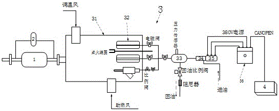
[0033] The present invention will be described in detail below in terms of specific embodiments in conjunction with the accompanying drawings. The following examples will help those skilled in the art to further understand the present invention, but do not limit the present invention in any form. It is to be noted that other embodiments may be utilized or structural and functional modifications may be made to the embodiments set forth herein without departing from the scope and spirit of the invention.

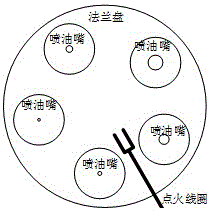
[0034] The burner is a combustion system that mixes fuel and air for combustion to provide high-temperature gas. Divided into several types such as industrial, civil and special. The burner simulation device 3 in this embodiment is a device for simulating a dedicated burner for an automobile exhaust system and after-treatment components.

[0035] The Diesel Particulate Filter 1 (Diesel Particulate Filter) in this embodiment is an exhaust post-treatment device installed in th...


PUM


Abstract

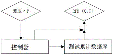
The invention provides a deposited carbon regeneration and thermal fatigue simulation testing system of a diesel fuel particulate trap. The deposited carbon regeneration and thermal fatigue simulation testing system comprises a diesel fuel particulate filter, a differential pressure transducer, a burner simulation device, and a controller. The gas inlet of the diesel fuel particulate filter is connected with the gas outlet of the burner simulation device, and the two probes of the differential pressure transducer are respectively connected with the gas inlet opening and the gas outlet opening of the diesel fuel particulate filter, and in addition, the differential pressure sensor and the burner simulation device are connected with the controller. The controller is used to control the flow and / or the temperature of the gas outlet of the burner simulation device according to preset configuration information or external input, and is used to acquire the deposited carbon regeneration characteristic parameter, and / or the thermal fatigue characteristic parameter, and / or the operation parameter of the diesel fuel particulate filter according to differential pressure signals received by the differential pressure transducer. A user testing technology is simplified, and by aiming at DPF of development of different engine models, testing curves and testing data packages matched with the different models are formed, and are used for development, researches, and subsequent tests.

Description

technical field [0001] The invention relates to the technical field of testing, in particular to a carbon deposition regeneration and thermal fatigue simulation testing system of a diesel particulate filter. Background technique [0002] With the country's emphasis on energy conservation and environmental protection, and the introduction of relevant laws and regulations, the market's emphasis on related fields is increasing. In the field of commercial vehicles, with the upgrade of the national team's automobile emission reduction regulations, the requirements for vehicle after-treatment systems are becoming increasingly stringent. For commercial vehicles, controlling the content of PM in engine exhaust gas is an important emission indicator for commercial vehicles. Diesel Particulate Filter (DPF, Diesel Particulate Filter) is the most effective means to purify the exhaust gas of commercial vehicles, and it is also one of the global emission reduction methods. Therefore, the ...

Claims


Application Information

Patent Timeline
IPC IPC(8): G01M13/00
CPCG01M13/00
Inventor 李松波
Owner SHANGHAI WAYEMER TECH CO LTD
Learn More