Fault oscilloscope working condition information remote monitoring, maintenance and rapid browsing system

A technology of fault recorder and working condition information, which is applied in the fault location and detection of faults according to conductor types, etc., can solve the problems of insufficient on-site coordination of fault recorder and no on-site inspection, and achieves low construction cost, The effect of low load bearing and reduction of failure loss

Inactive Publication Date: 2017-03-15
PINGDINGSHAN POWER SUPPLY ELECTRIC POWER OF HENAN
View PDF7 Cites 4 Cited by
  • Summary
  • Abstract
  • Description
  • Claims
  • Application Information

AI Technical Summary

Problems solved by technology

However, this invention does not have an on-site inspection method, and the on-site cooperation with the fault recorder is not enough

Method used


Image

  • Fault oscilloscope working condition information remote monitoring, maintenance and rapid browsing system
  • Fault oscilloscope working condition information remote monitoring, maintenance and rapid browsing system
  • Fault oscilloscope working condition information remote monitoring, maintenance and rapid browsing system

Examples


Embodiment 1

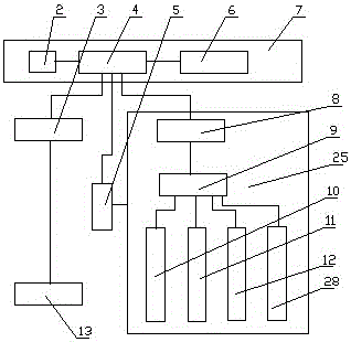
[0029] Such as Figure 1 to Figure 4 As shown: this embodiment provides a remote monitoring, maintenance and quick browsing system for fault recorder working condition information, including several fault recorders 13 arranged on the transmission line, a monitoring center 7 and a mobile device connected to it Type monitoring unit, described mobile monitoring unit comprises the overhead rail 16 that is arranged along grid line, the rail car 24 that is arranged on described overhead rail 16 and positioning device 5, the monitoring terminal 25 that is set on described rail car 24, described monitoring The terminal 25 includes a sensor module 10, a control module 9, a video monitoring module 11, a first communication module 8 and a UHF omnidirectional sensor receiving and amplifying module 12 that is rotatably arranged on the rail car, and the control module 9 and the sensor module 10, The video monitoring module 11, the first communication module 8 are connected with the UHF omni...

Embodiment 2

[0037] Such as Figure 1 to Figure 4 Shown: its difference with embodiment one is:

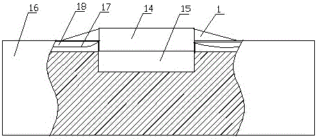
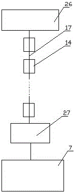
[0038] The positioning device 5 includes several sensor slots 15 arranged at intervals on the overhead track 16, and fiber grating sensors 14 are arranged in the sensor slots 15, and the several fiber grating sensors 14 are connected by transmission optical fibers 17. The top of the fiber grating sensor 14 is higher than the upper edge of the sensor groove 15 , and the transmission optical fiber 17 is arranged in the cavity 18 arranged on the overhead track 16 . The fiber grating sensor can realize the direct measurement of physical quantities such as temperature and strain. When the wheel of the traveling mechanism is pressed on the fiber grating sensor, it will be strained, so that it is detected whether the traveling mechanism reaches the top of the fiber grating sensor, thus realizing the fixed-point Radiation measurement.

[0039] The top of the fiber grating sensor 14 is 0.5 cm to 1 cm...

Embodiment 3

[0043] Such as Figure 1 to Figure 4 Shown: its difference with embodiment one is:

[0044] The hanging mechanism comprises an L-shaped bracket 32 ​​provided at the lower end of the rail car 24 and two U-shaped arms 30 arranged at the upper end of the aircraft 28, and the open end of the L-shaped bracket 32 ​​is provided with a telescopic frame at the lower end of the rail car 24. Rod 29, the telescopic rod 29 is connected with the control module 9, and the aircraft 28 adopts a quadrotor UAV. When the aircraft is not in use, it is hung on the L-shaped bracket through two U-shaped arms, and then the opening of the L-shaped bracket is blocked by the telescopic rod to prevent the U-shaped arm from slipping off the L-shaped bracket. When in use, the telescopic control is controlled by the control module The arm is retracted, and the aircraft can fly out from the L-shaped support. The aircraft adopts a quadrotor drone, the stability of the fuselage is better maintained, and it is...


PUM


Abstract

The invention discloses a fault oscilloscope working condition information remote monitoring, maintenance and rapid browsing system. The system comprises fault oscilloscopes, a monitoring center and a monitoring unit, wherein the mobile monitoring unit comprises an overhead track along a power grid line, a rail car and a positioning mechanism which are arranged on the overhead track, and a monitoring terminal arranged on the rail car, the monitoring terminal comprises a sensor module, a control module, a video monitoring module, a first communication module and an ultrahigh-frequency omnidirectional sensor receiving amplification module, the fault oscilloscopes are connected with the monitoring center through the second communication module, the lower end of the rail car is provided with an aircraft through a suspension mechanism, and the lower end of the aircraft is rotationally provided with the ultrahigh-frequency omnidirectional sensor receiving amplification module. According to the invention, whole power grid information and equipment information can be monitored merely by use of a small amount of sensors, and through cooperation with the fault oscilloscopes of the power grid line, fault points are timely and rapidly sought and positioned.

Description

technical field [0001] The invention relates to the technical field of smart grid fault diagnosis, in particular to a remote monitoring, maintenance and quick browsing system for working condition information of a fault recorder. Background technique [0002] The fault recorder is used in the power system. When the system fails, it can automatically and accurately record the changes of various electrical quantities in the process before and after the fault. Through the analysis and comparison of these electrical quantities, it can analyze and handle accidents and judge It plays an important role in whether the protection operates correctly and improves the safe operation level of the power system. The fault recorder is an important automatic device to improve the safe operation of the power system. When the power system fails or oscillates, it can automatically record the changes of various electrical quantities during the entire fault process. Because of the important role...

Claims


Application Information

Patent Timeline
Patent Type & Authority Applications(China)
IPC IPC(8): G01R31/08
CPCG01R31/086
Inventor 汪峰刘春阳智勇军李晓航陆畅周志锋李庆盈杨玉良周春雷
Owner PINGDINGSHAN POWER SUPPLY ELECTRIC POWER OF HENAN
Why Eureka
Try Eureka