
Recurrent laryngeal nerve real-time monitor and monitoring method

A real-time monitor and real-time monitoring technology, which is applied in the medical field, can solve problems such as difficult insertion depth and vocal cord damage for the implementer, and achieve the effect of avoiding vocal cord damage and low requirements

Pending Publication Date: 2017-03-22
肖玉根
View PDF3 Cites 2 Cited by
  • Summary
  • Abstract
  • Description
  • Claims
  • Application Information

AI Technical Summary

Problems solved by technology

[0002] In thyroid ablation surgery, the real-time monitoring of laryngeal reflex nerve is particularly important, which is also the difficulty of the operation. In the prior art, electrodes are placed on the nerve endotracheal tube, the nerve endotracheal endotracheal tube is connected to the junction box, and then the nerve endotracheal endotracheal tube is connected The cannula is inserted into the patient's body, and finally the surgical instruments connected to the junction box send out micro-stimulation currents to stimulate the nerves to obtain myoelectric signals. The technical plan must be under the state of general anesthesia of the patient, and when it is implemented, the implementer must accurately grasp the insertion depth. Too deep or too shallow will lead to the failure of real-time monitoring of the recurrent laryngeal nerve. Under different physiological conditions of different patients , it is difficult for the implementer to accurately control the insertion depth of the neurotracheal tube with electrodes, and when the neurotracheal tube with electrodes is exposed, it is easy to cause damage to the patient's vocal cords because the electrodes are exposed. Therefore, a Real-time monitoring of laryngeal reflex nerve can be realized under semi-anesthesia, and monitors and monitoring methods that do not damage human vocal cords are in urgent need of research

Method used


Image

  • Recurrent laryngeal nerve real-time monitor and monitoring method

Examples


Embodiment Construction

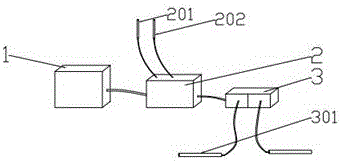
[0014] like figure 1 , the present invention includes a host 1, an interface box 2 electrically connected to the host, the interface box 2 includes a positive electrode needle 201 and a negative electrode needle 202, the interface box 2 is electrically connected to a junction box 3, and the junction box 3 includes A plurality of surgical instruments 301, the positive electrode needles 201 and the negative electrode needles 202 are electrically connected to the interface box 2. During the operation, the positive electrode needles 201 and the negative electrode needles 202 are respectively inserted into the two sides of the thyroid cartilage notch. At this time, the positive electrode needle 201 and the negative electrode needle 202 will generate two circuits, one is the vocal cord muscle attached to the thyroid cartilage and the recurrent laryngeal nerve to form a circuit, and the other is the neuromuscular junction attached to the thyroid cartilage to form a circuit with the va...


PUM


Abstract

The invention discloses a recurrent laryngeal nerve real-time monitor and a monitoring method. The monitor comprises a host, an interface box and a branch box, and is characterized in that the interface box comprises a positive electrode needle and a negative electrode needle, the branch box is electrically connected with a surgical instrument, the host is electrically connected to the branch box through the interface box, and the positive electrode needle and the negative electrode needle are connected to the interface box. The monitoring method includes the steps: first, inserting the positive electrode needle and the negative electrode needle to two sides of a thyroid cartilage notch respectively, and forming a loop between a vocal muscle and a recurrent laryngeal nerve; second, stimulating the recurrent laryngeal nerve by the surgical instrument with weak current. At the moment, the vocal muscle vibrates to form myoelectric signals, and the myoelectric signals are transmitted into the host through the interface box and analyzed to monitor the recurrent laryngeal nerve in real time. Real-time monitoring can be realized in a twilight anesthesia state, and a vocal cord cannot be injured while the nerve is monitored.

Description

technical field [0001] The invention relates to the medical field, in particular to a real-time monitor for laryngeal reflex nerve and a monitoring method. Background technique [0002] In thyroid ablation surgery, the real-time monitoring of laryngeal reflex nerve is particularly important, which is also the difficulty of the operation. In the prior art, electrodes are placed on the nerve endotracheal tube, the nerve endotracheal endotracheal tube is connected to the junction box, and then the nerve endotracheal endotracheal tube is connected The cannula is inserted into the patient's body, and finally the surgical instruments connected to the junction box send out micro-stimulation currents to stimulate the nerves to obtain myoelectric signals. The technical plan must be under the state of general anesthesia of the patient, and when it is implemented, the implementer must accurately grasp the insertion depth. Too deep or too shallow will lead to the failure of real-time mo...

Claims


Application Information

Patent Timeline
Patent Type & Authority Applications(China)
IPC IPC(8): A61B5/0488A61B5/0492A61B5/296
CPCA61B5/4041A61B2562/0209A61B5/389A61B5/296
Inventor 肖玉根
Owner 肖玉根
Learn More