Turbulent flow and chemical agglomeration coupling fine particle agglomeration device

A technology of chemical agglomeration and fine particles, applied in chemical instruments and methods, separation of dispersed particles, separation of electrostatic effects, etc., can solve the problems of changing the surface of particles and increasing the effective collision between particles, so as to achieve simple equipment, increase adhesion, The effect of low investment cost

Active Publication Date: 2017-03-22
QINGDAO UNIV
View PDF7 Cites 13 Cited by
  • Summary
  • Abstract
  • Description
  • Claims
  • Application Information

AI Technical Summary

Problems solved by technology

The agglomeration device uses spoiler columns and vortex plates to generate turbulent disturbance to the flue gas flow field, increasing the effective collision between particles;

Method used


Image

  • Turbulent flow and chemical agglomeration coupling fine particle agglomeration device

Examples


Embodiment Construction

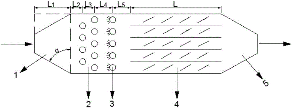
[0016] .combined with figure 1 The flow and chemical agglomeration coupled fine particle agglomeration device of the present invention is described. The agglomeration device includes a flue gas inlet enlargement section 1, a turbulent flow initial section 2, an atomization section 3, a vortex turbulence section 4, and an outlet narrowing section 5. The agglomeration device is a three-dimensional vertical equipment with a section of 250×450mm and a length of 2470mm. The lengths of the flue gas inlet enlarged section 1 and the outlet narrowed section 5 are respectively 235 mm (L1 = 235 mm), and the angle α between the inlet or outlet and the flue gas flow direction is 60°. The length of the turbulent flow section 4 of the vortex slices is 1300mm (L=1300mm), and it is divided into 5 micro-sections with a steel plate with a thickness of 1.5mm, equipped with 4 sets of vortex slices, the distance between each set of vortex slices is 260mm, and each set of vortex slices contains 4 T...


PUM


Abstract

The invention relates to a turbulent flow and chemical agglomeration coupling fine particle agglomeration device. The device mainly and structurally comprises a flue gas inlet magnification section, a turbulent flow initial subsection, an atomization section, a vortex sheet turbulent section and an outlet shrinkage section. The flue gas inlet magnification section and the outlet shrinkage section are a smooth inlet and outlet, the turbulent flow initial subsection is provided with two-layer circular turbulent columns placed in a staggered mode, preliminary flow division is performed on particles in smoke, a dual-fluid atomization nozzle atomizes a mixed chemical agglomeration agent and sprays the mixed chemical agglomeration agent into a small-particle vortex region of an agglomeration room at the atomization section, the vortex sheet turbulent section is equally divided into differential regions by means of slabs, vortex sheets are placed into the differential regions for strengthening collision between fine particles and collision between atomization liquid drops and particles, fine particle agglomeration and growth are promoted, and then the fine particle removal efficiency of follow-up dust removal equipment is improved.

Description

technical field [0001] The invention belongs to the field of flue gas dust removal, and in particular relates to a device for agglomerating and removing fine particles in coal-fired flue gas under the coupled action of turbulent flow and chemical agglomeration. Background technique [0002] Energy and the environment are the basic conditions for the survival and development of human beings in the 21st century. While energy promotes economic development, it also brings environmental pollution. In my country's energy structure, the dominant position of coal as a primary energy source is difficult to change for a long time, and the combustion of fossil fuels such as coal is the main source of particulate matter. In the air pollution of cities in my country, particulate matter pollution is also the primary pollutant, especially the aerodynamic diameter less than 2.5 μm (PM 2.5 ) of fine particles. Fine particles in the air are easily inhaled by the nose and mouth, and are clos...

Claims


Application Information

Patent Timeline
IPC IPC(8): B01D51/02B03C3/01
CPCB01D51/02B01D2258/0283B03C3/013
Inventor 孙德帅张晓东杜辉陈照军
Owner QINGDAO UNIV
Why Eureka
Try Eureka