Brake baseplate machining fixture

A brake base plate and fixture technology, applied in the direction of manufacturing tools, metal processing equipment, metal processing machinery parts, etc., can solve the problems of high processing cost, low work efficiency, high labor intensity for changing models, etc., and achieves convenient use and simple structure. Effect

Inactive Publication Date: 2017-03-22
JINGZHOU HENGFENG BRAKE SYST CO LTD
View PDF8 Cites 2 Cited by
  • Summary
  • Abstract
  • Description
  • Claims
  • Application Information

AI Technical Summary

Problems solved by technology

[0003] The purpose of the present invention is to provide a simple structure, easy to use, suitable for clamping various types and types of brake base plates, so as to solve the labor of changing types when using the existing clamps to clamp the brake base plate. Brake bottom plate processing fixture with high strength, low work efficiency and high processing cost

Method used


Image

  • Brake baseplate machining fixture
  • Brake baseplate machining fixture
  • Brake baseplate machining fixture

Examples


Embodiment Construction

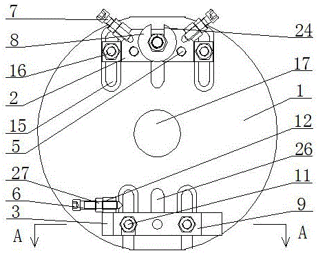
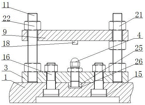
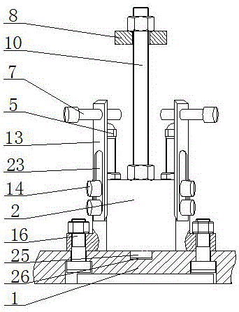
[0020] The brake bottom plate processing fixture is composed of a bottom plate 1, a mounting seat 2, a mounting plate 3, a support nail A4, a support nail B5, a positioning nail A6, a positioning nail B7, a pressing block 8, a pressing plate 9, a pressing screw 10 and a fastening screw 11. The bottom plate 1 is evenly distributed with strip-shaped sliding holes 15; the mounting plate 3 and the mounting seat 2 are arranged symmetrically to each other, and are fixedly connected to the strip-shaped sliding holes 15 through T-shaped bolts 16 respectively. After setting in this way, people can adjust the distance between the mounting plate 3 and the mounting base 2 according to the size of the brake base plate, so that the processing fixture is suitable for clamping various brake base plates.

[0021] The bottom ends of the mounting plate 3 and the mounting seat 2 are respectively provided with guide rails 25 ; the bottom plate 1 below the guide rails 25 is provided with guide groov...


PUM


Abstract

The invention relates to a brake baseplate machining fixture, and belongs to the technical field of brake baseplate machining equipment. The machining fixture consists of a baseplate, support nails B, a positioning nail A, a positioning nail B, a pressing block, a pressing plate, a pressing screw rod and fastening screw rods; a mounting plate and a mounting base are symmetrically arranged on the baseplate; the positioning nail A is mounted on the inner side of one end of the mounting plate through a mounting block by a thread; the pressing plate is mounted above the mounting plate through the fastening screw rods symmetrically arranged; the support nail A is fixedly mounted below the pressing plate; the pressing block is arranged at the upper end of the mounting base through the pressing screw rod; and the support nails B are symmetrically arranged on the inner side of the pressing screw rod. The brake baseplate machining fixture is simple in structure and convenient to use, solves the problems of high model change labor intensity, low working efficiency and high machining cost in clamping of the brake baseplate by a traditional fixture, and satisfies the clamping demands of the brake baseplate.

Description

technical field [0001] The invention relates to a clamp for processing a brake bottom plate, which belongs to the technical field of brake bottom plate processing equipment. Background technique [0002] As the basic component of the brake, the brake base plate needs to be processed in sequence by casting and finishing before it can meet the requirements of use. In the process of finishing the brake base plate after casting, it is necessary to turn the center hole of the brake base plate first, and then proceed to the next process with the center hole positioning. Therefore, the processing of the middle hole of the brake bottom plate is the basis of the finishing of the brake bottom plate. At present, the processing of the middle hole of the brake bottom plate is mainly clamped by special fixtures. However, there are many types of brake bottom plates, and there are many models. For different types and types of brake base plates, different fixtures are required to complete ...

Claims


Application Information

Patent Timeline
IPC IPC(8): B23Q3/00
CPCB23Q3/00B23Q2703/10
Inventor 罗成
Owner JINGZHOU HENGFENG BRAKE SYST CO LTD
Why Eureka
Try Eureka