Air conditioner unit platform of urban rail vehicle

A technology for air-conditioning units and urban rail vehicles, which is applied in the heating/cooling of railway vehicles, railway car body parts, transportation and packaging, etc., and can solve problems such as inability to meet the needs of rainwater drainage, high flatness requirements, and large weld lengths , to achieve the effect of reducing manual welding, improving platform flatness and sealing performance, and good sealing performance

Inactive Publication Date: 2017-03-22
CRRC DALIAN CO LTD
View PDF7 Cites 1 Cited by
  • Summary
  • Abstract
  • Description
  • Claims
  • Application Information

AI Technical Summary

Problems solved by technology

[0005] The existing technology has the following disadvantages: (1) Since the air supply and return chambers of the platform are arranged side by side along the vehicle length direction, the return air chamber is in the middle, and the air supply chamber is on both sides of the return air chamber
For the ground line, only through the drainage groove, it cannot meet the needs of rainwater drainage
[0007] (3) The platform skin is lapped by two skins, and the lap joint is welded along the vehicle length direction, the weld length is large, and the deformation is large, especially at the lap joint position of the lower part of the sealing frame, the sealing performance is poor;
[0008] (4) The vertical plates at both ends of the platform are welded to the skin along the width direction of the vehicle (such as image 3 As shown), the length of the weld is large, the amount of deformation is large, and the sealing is poor;
[0009] (5) There are three sealing frames on the upper part of the platform skin (one return air chamber 2b and two air supply chambers 2a). The installation of the air conditioning unit has high requirements on the flatness of the three installation surfaces, which is prone to air leakage

Method used


Image

  • Air conditioner unit platform of urban rail vehicle
  • Air conditioner unit platform of urban rail vehicle
  • Air conditioner unit platform of urban rail vehicle

Examples


Embodiment Construction

[0031] The present invention will be further described below in conjunction with accompanying drawing.

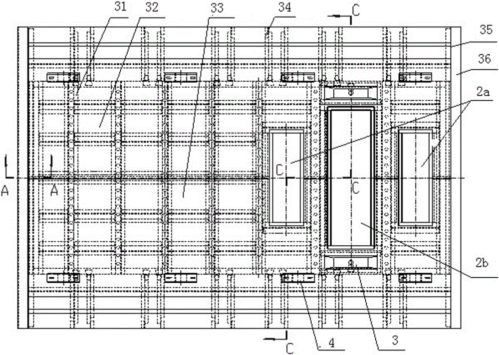
[0032] Such as Figure 5-Figure 13 As shown, on the platform of the air-conditioning unit of the urban rail vehicle, the frame 1 is welded with the sealing frame 2, the drainage groove 3 and the mounting seat 4, and the sealing frame 2 is provided with the air supply chamber 2a and the return air chamber 2b, and the air supply chamber 2a and the return air chamber 2b is arranged parallel to the vehicle width direction. According to the continuity requirements of the air supply duct of the vehicle air duct system along the vehicle length direction, determine the arrangement of the air supply outlets and return air outlets along the vehicle width direction.

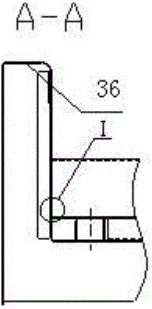
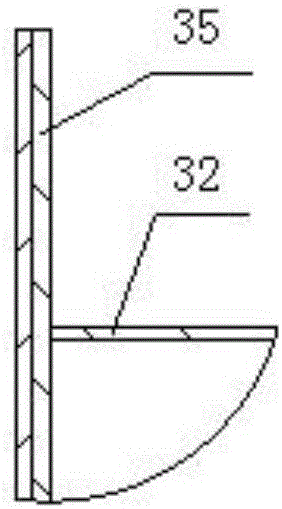
[0033] The skeleton 1 is cross-welded by the skeleton longitudinal beam 11 and the skeleton cross beam 12, the longitudinal beam 13 is welded at the upper and lower ends, the skin support beam 14 is welded at the left a...


PUM


Abstract

Disclosed is an air conditioner unit platform of an urban rail vehicle. A sealing frame, a water draining groove and an installation seat are welded to a framework. An air feeding cavity and an air returning cavity are formed in the sealing frame and distributed parallel to the vehicle width direction. The framework is formed by welding framework longitudinal beams and framework transverse beams in an intersecting mode, welding longitudinal beams to the upper end and the lower end, welding skin supporting beams to the left end and the right end, and welding skin to the framework longitudinal beam, the framework transverse beam, the longitudinal beams and the skin supporting beams in a covering mode. The air conditioner unit platform of the urban rail vehicle is beneficial to adjustment and control of air feeding uniformity. A protruding reinforcement beam structure on an existing platform is omitted, the levelness of the upper structure of the platform is realized, the water draining requirement of the top of the vehicle is met, manual welding is reduced, production efficiency is improved, the deformation amount of skin welding is effectively lowered, and the sealing performance of the platform is improved.

Description

technical field [0001] The invention relates to a vehicle air-conditioning unit platform, in particular to a stainless steel urban rail vehicle air-conditioning unit platform. Background technique [0002] The air-conditioning and ventilation systems of stainless steel urban rail vehicles mostly use top-mounted unit-type air-conditioning units, and each vehicle is equipped with two units, which are installed on the air-conditioning unit platform on the top of the car body. According to the use and structural needs of the air conditioning unit, its ventilation mode is mainly divided into end-out and end-return, end-out and next-return, and bottom-out and next-return. In addition to providing reliable support for the installation of the air-conditioning unit on the top of the car body and meeting the strength requirements of the car body, the platform of the air-conditioning unit on the top of the car body also needs to solve the problem of discharge of condensed water and rai...

Claims


Application Information

Patent Timeline
Patent Type & Authority Applications(China)
IPC IPC(8): B61D27/00
CPCB61D27/00
Inventor 关显涛臧兰兰曲晓梅孙闯郭蕾曹津铭
Owner CRRC DALIAN CO LTD
Why Eureka
Try Eureka