[0029] The following will clearly and completely describe the technical solutions in the embodiments of the present invention with reference to the accompanying drawings in the embodiments of the present invention. Obviously, the described embodiments are only some, not all, embodiments of the present invention. Based on the embodiments of the present invention, all other embodiments obtained by persons of ordinary skill in the art without making creative efforts belong to the protection scope of the present invention.
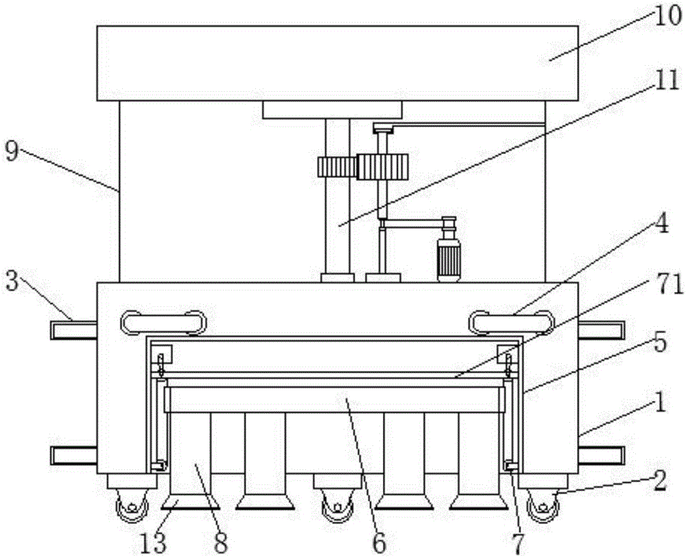
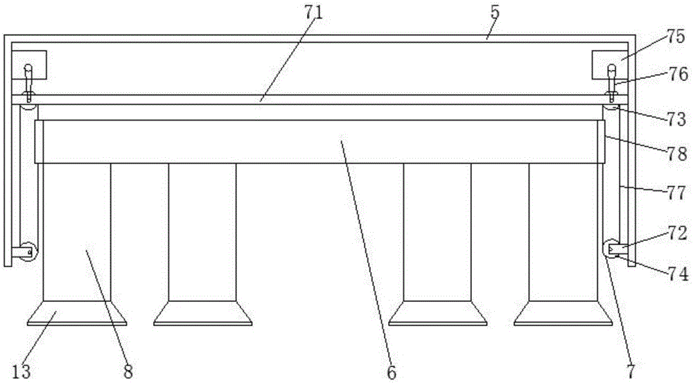
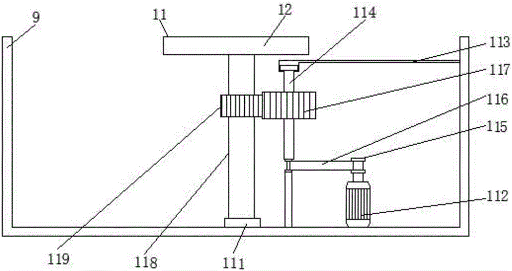
[0030] like Figure 1-4 As shown, the present invention provides a technical solution: a convenient mobile electronic communication placement device, including a first box body 1, through the setting of the first box body 1, the first box body 1 plays a role in its internal devices. The function of protection, the bottom of the first box body 1 is provided with a moving wheel 2, the moving wheel 2 includes a horizontal block, the bottom of the horizontal block is fixedly installed with a vertical plate, and the bottom of the vertical plate is movably connected with a roller, the setting of the moving wheel 2 is convenient For the movement of the device, both sides of the first box body 1 are fixedly equipped with a lifting handle 3, and the setting of the lifting handle 3 facilitates the lifting of the device. The surface of the first box body 1 is fixedly installed with a push handle 4, The setting of push handle 4 has made things convenient for the promotion of this device and has force point, and the inside of first box body 1 is fixedly installed with second box body 5, and the setting of second box body 5, second box body 5 acts on the device inside it. To protect the function, the inside of the second box body 5 is provided with a horizontal plate 6, the horizontal plate 6 has played the role of connection, the bottom of the horizontal plate 6 is fixedly connected with one end of the support column 8, and the bottom of the support column 8 is fixedly installed with a contact Plate 13, the setting of contact plate 13 has increased contact area, and contact plate 13 is rectangular structure, and the bottom of contact plate 13 is fixedly installed with anti-slip pad, and the surface of anti-slip pad is provided with anti-slip thread, and anti-slip pad has the effect of anti-skid, and support column The other end of 8 passes through the second box body 5 and the first box body 1 and extends to the outside of the first box body 1. Lifting and fixing devices 7 are arranged on both sides of the horizontal plate 6, and the top of the first box body 1 is fixed A third box body 9 is installed, the top of the third box body 9 is in contact with the bottom of the placement table 10 , and a rotating device 11 is arranged inside the third box body 9 .
[0031] The lifting and fixing device 7 includes a first support plate 71 and a second support plate 72, the first support plate 71 is movably connected with a drive wheel 73, the second support plate 72 is movably connected with a drive wheel 74, and the drive wheel 73 is positioned at the drive wheel 74 and the diameter of the driving wheel 73 is the same as that of the driving wheel 74, the axis of the driving wheel 73 is connected with the output shaft of the first forward and reverse motor 75 fixedly installed inside the second box body 5 through a transmission belt 76, and the first forward rotation The power supply mode of the reversing motor 75 is powered by an external power supply, the first support plate 71 and the second support plate 72 are connected by a transmission belt 77, and the side of the conveyor belt 77 away from the inner wall of the second box body 5 is connected to the connecting block 78 One side of the connecting block 78 is fixedly connected, the length of the connecting block 78 is equal to the width of the horizontal plate 6, and the other side of the connecting block 78 is fixedly connected to one side of the horizontal plate 6, through the first support plate 71, the second support plate 72, Drive wheel 73, driving wheel 74, the first reversing motor 75, conveyer belt 76, conveyer belt 77 and connecting block 78 are used in conjunction to achieve the effect of lifting and fixing, which facilitates the adjustment of the height of lifting handle 3 and facilitates the work. The person lifts the device, and the setting of the moving wheel 2 facilitates the movement.
[0032]The rotating device 11 includes a rotating disc 111, one side of the rotating disc 111 is provided with a vertical rod 114, one side of the vertical rod 114 is provided with a second forward and reverse motor 112, and the power supply mode of the second forward and reverse motor 112 is through an external power supply, the output shaft of the second forward and reverse motor 112 is fixedly connected to the bottom of the take-up wheel 115, the bottom of the second forward and reverse motor 112 is fixedly connected to the bottom of the third box body 9 inner cavity, and the third box body 9 One side of the inner cavity is fixedly equipped with a cross bar 113, and the vertical bar 114 is movably connected between the third box body 9 and the cross bar 113. connection, the surface of the vertical bar 114 is sleeved with a driving gear 117, the driving gear 117 is located above the transmission belt 116, the top of the rotating disk 111 is fixedly connected with a rotating rod 118, and the surface of the rotating rod 118 is sleeved with a driving gear that meshes with the driving gear 117. Gear 119, through the cooperative use of rotating disc 111, the second forward and reverse motor 112, cross bar 113, vertical bar 114, take-up wheel 115, transmission belt 116, driving gear 117, rotating rod 118 and driving gear 119, has reached rotation effect, facilitates the rotation of electronic communication equipment, improves the utilization rate, and facilitates the use of workers. The top of the vertical bar 114 is fixedly connected with the bottom of the connecting bar 12, and the top of the connecting bar 12 is fixedly connected with the bottom of the placing table 10. , the four faces of the inner cavity of the placing table 10 are all fixedly equipped with compression springs 14, and one end of the four compression springs 14 is all fixedly installed with a pad 15, and the shape of the pad 15 is set to a semicircle. The combined use of the spring 14 and the pad 15 facilitates the placement of the electronic communication equipment, stabilizes the electronic communication equipment, and protects the electronic communication equipment.
[0033] During work, by people pushing the handle 4, the moving wheel 2 drives the device to move under the device, and the first forward and reverse motor 75 rotates, and the output shaft of the first forward and reverse motor 75 drives the driving wheel 73 to rotate through the conveyor belt 76 , the drive wheel 73 rotates through the conveyor belt 77 to drive the drive wheel 74 to rotate, the connecting block 78 on the conveyor belt 77 moves with it, the horizontal plate 6 drives the support column 8 to move with the movement of the connecting block 78, and the contact plate 13 moves with the movement of the connecting block 78. The movement of the support column 8 moves to achieve the stable effect of the device. The worker can adjust the height suitable for the work as required, and rotate through the rotating device 11. The output shaft of the rotating device 11 rotates the belt take-up pulley 115 to rotate, and the transmission belt 116 follows the The rotation of the take-up wheel 115 drives the vertical bar 114 to rotate, the driving gear 117 drives the driving gear 119 to rotate along with the rotation of the vertical bar 114, and the rotating rod 118 drives the connecting bar 12 to rotate along with the movement of the driving gear 119, and the connecting bar 12 The rotation drives the placement platform 10 to rotate until the communication equipment on the placement platform 10 reaches the direction required by the worker.
[0034] In summary, the easy-to-move placing device for electronic communication is passed through the first supporting plate 71, the second supporting plate 72, the driving wheel 73, the driving wheel 74, the first forward and reverse motor 75, the conveyor belt 76, and the conveyor belt 77. Cooperating with the connection block 78, the effect of lifting and fixing is achieved, which facilitates the adjustment of the height of the lifting handle 3, facilitates the worker to lift the device, and facilitates the movement by setting the moving wheel 2.
[0035] In addition, the mobile electronic communication placement device is driven by the rotating disk 111, the second forward and reverse motor 112, the cross bar 113, the vertical bar 114, the winding wheel 115, the transmission belt 116, the driving gear 117, the rotating rod 118 and the drive The cooperating use of the gear 119 achieves the effect of rotation, facilitates the rotation of electronic communication equipment, improves the utilization rate, and facilitates the use of workers.
[0036] In addition, the easy-to-move placement device for electronic communication facilitates the placement of electronic communication equipment, stabilizes the electronic communication equipment, and protects the electronic communication equipment through the cooperation of the placement table 10, the compression spring 14 and the pad 15. role.
[0037] Simultaneously, this easy-to-move placement device for electronic communication achieves the effect of increasing the contact area between the support column 8 and the ground through the cooperative use of the contact plate 13 and the anti-skid pad, and simultaneously achieves the effect of anti-skid. Cooperating with the push handle 4, it is convenient for workers to move the electronic communication equipment.
[0038] At the same time, the mobile electronic communication placement device is reasonable in design, strong in applicability, and easy to popularize and use.
[0039] It should be noted that in this article, relational terms such as first and second are only used to distinguish one entity or operation from another entity or operation, and do not necessarily require or imply that there is a relationship between these entities or operations. There is no such actual relationship or order between them. Furthermore, the term "comprises", "comprises" or any other variation thereof is intended to cover a non-exclusive inclusion such that a process, method, article, or apparatus comprising a set of elements includes not only those elements, but also includes elements not expressly listed. other elements of or also include elements inherent in such a process, method, article, or device. Without further limitations, an element defined by the phrase "comprising a ..." does not exclude the presence of additional identical elements in the process, method, article or apparatus comprising said element.
[0040] Although the embodiments of the present invention have been shown and described, those skilled in the art can understand that various changes, modifications and substitutions can be made to these embodiments without departing from the principle and spirit of the present invention. and modifications, the scope of the invention is defined by the appended claims and their equivalents.