Part tray lifting mechanism

A technology of pallet lifting and parts, applied in conveyors, conveyor objects, transportation and packaging, etc., can solve problems such as low efficiency, affecting production rhythm, and poor safety.

Inactive Publication Date: 2017-03-22
WUXI MINGZHU STEEL BALL
View PDF12 Cites 4 Cited by
  • Summary
  • Abstract
  • Description
  • Claims
  • Application Information

AI Technical Summary

Problems solved by technology

[0002] The parts pallet transported from the parts assembly line needs to be transferred to the next process. The working position of the tooling in this process is often at a diff

Method used


Image

  • Part tray lifting mechanism
  • Part tray lifting mechanism
  • Part tray lifting mechanism

Examples


Embodiment Construction

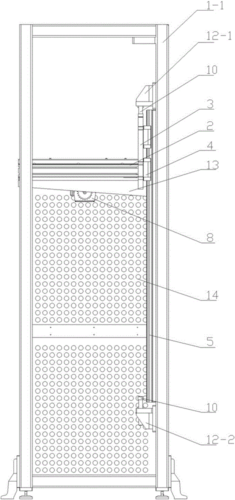
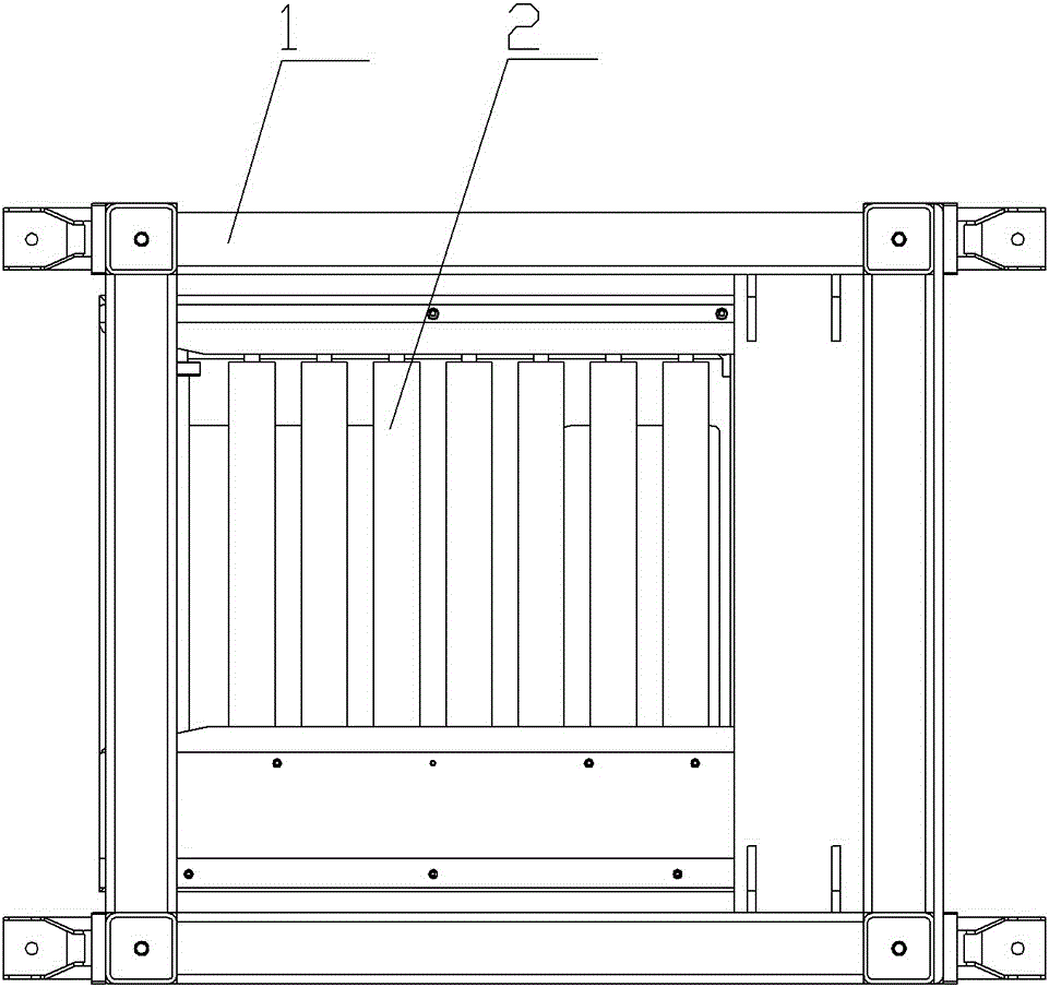
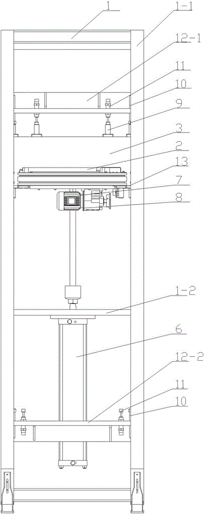
[0020] figure 1 , figure 2 , image 3 , Figure 4 Middle: frame 1, support frame 1-1, support plate 1-2; roller conveying seat 2, roller 2-1, inclined guide plate 2-2; lifting seat 3; guide rail 4; slider 5; cylinder 6; transmission Motor 7, mounting frame 8; sleeve 9; limit post 10, buffer limit post 11; upper limit mounting plate 12-1, lower limit mounting plate 12-2; fixed plate 13; protective plate 14.

[0021] see Figure 1-Figure 4 As shown, a parts pallet lifting mechanism includes a frame 1, a roller conveying seat 2, on which a roller 2-1 is arranged, and a plurality of parallel rollers 2-1 arranged side by side pass through a sprocket (in the figure) Not expressed) connected together so that the rollers on the roller conveying seat 2 can rotate synchronously, the sprocket is connected to the transmission motor 7, and the two ends of the roller 2-1 on the roller conveying seat 2 are respectively provided with inclined guide plates 2 -2. The parts tray channel is formed...


PUM


Abstract

The invention provides a part tray lifting mechanism. The part tray lifting mechanism can be adapted to a part assembly line and can automatically transfer part trays on the part assembly line to next tool equipment at a work height different from that of the part assembly line. The part tray lifting mechanism comprises a rack and a roller conveying seat, rollers are distributed on the roller conveying seat, the multiple rollers arranged side by side are connected together through a chain wheel, and the chain wheel is connected with a transmission motor. The part tray lifting mechanism is characterized in that the part tray lifting mechanism furthermore comprises a lifting seat, an air cylinder and a limiting structure; the lifting seat is slidably installed on the rack through guide rails, the side of the lifting seat is connected with the roller conveying seat, and the bottom of the lifting seat is connected with the air cylinder; the limiting structure is installed on the rack and comprises limiting pillars; and the lifting seat is furthermore provided with an inductive switch, and the inductive switch is in electric control connection with the transmission motor.

Description

Technical field [0001] The invention relates to the technical field of assembly parts transportation, in particular to a parts tray lifting mechanism. Background technique [0002] The parts pallet transported from the part assembly line needs to be transferred to the next process. The working position of the tooling in this process is often at a different working height from the part assembly line. The common technique in the prior art is manual handling, which is inefficient and affects the production cycle. , Poor security. Summary of the invention [0003] In order to solve the existing technical problems, the present invention provides a part tray lifting mechanism, which can be adapted to the part assembly line, and can automatically transfer the part tray from the part assembly line to the next tooling equipment that is at a different working height from the part assembly line . [0004] The technical solution is as follows: it includes a frame and a roller conveying seat, ...

Claims


Application Information

Patent Timeline
IPC IPC(8): B65G47/57
CPCB65G47/57B65G2201/0267
Inventor 吴昊
Owner WUXI MINGZHU STEEL BALL
Why Eureka
Try Eureka