
Transformer station suspension bracket pedestal and spare transformer station suspension bracket

A technology for substations and hangers, applied to cranes and other directions, can solve the problems of out of reach, lifting height, long time, and long construction period, and achieve the effect of stable support and convenient movement

Inactive Publication Date: 2017-03-22
DONGMING POWER SUPPLY CO STATE GRID SHANDONG ELECTRIC POWER CO
View PDF7 Cites 13 Cited by
  • Summary
  • Abstract
  • Description
  • Claims
  • Application Information

AI Technical Summary

Problems solved by technology

Due to the large size of the crane, it is used in the live equipment area. The swing and lifting of the boom are limited by the site space and the surrounding live equipment. The operation is very inconvenient and there are serious accident hazards. Sometimes the power outage area has to be expanded to meet the Conditions of Use
For example, when replacing a 110kV outdoor current transformer, the current transformer is generally located behind the switch, the crane is fixed on the ground, and the lifting arm must pass through the switch to lift the transformer, and the lifting height of the lifting arm is affected by the passing line above, swinging The angle is limited by the switch; for another example, when replacing the 110kV bus PT, its installation position or the crane cannot reach it, or the lifting height is affected by the live bus above; another example is to replace or install the outdoor 110kV A (side) switch, 35kV outdoor switch , 110kV line PT and other operations, there are cases where lifting equipment is limited by site conditions and the scope of power outages is expanded, and even lifting equipment cannot be used.
If a forklift is used, there are problems such as insufficient lifting height, heavy dead weight, and inconvenient transportation.
This type of operation is very common in substation maintenance or installation and expansion projects. The use of existing technologies greatly affects the progress of the project. Not only does the construction period take a long time, but it often results in large-scale and long-term power outages, reducing power transmission and transformation efficiency, and The operation safety factor is low, so far, this problem has not been solved ideally

Method used


Image

  • Transformer station suspension bracket pedestal and spare transformer station suspension bracket
  • Transformer station suspension bracket pedestal and spare transformer station suspension bracket
  • Transformer station suspension bracket pedestal and spare transformer station suspension bracket

Examples


Embodiment 1

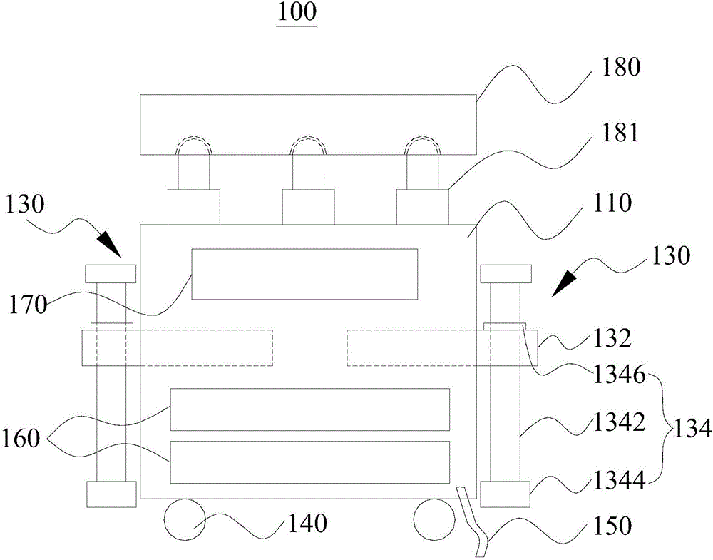
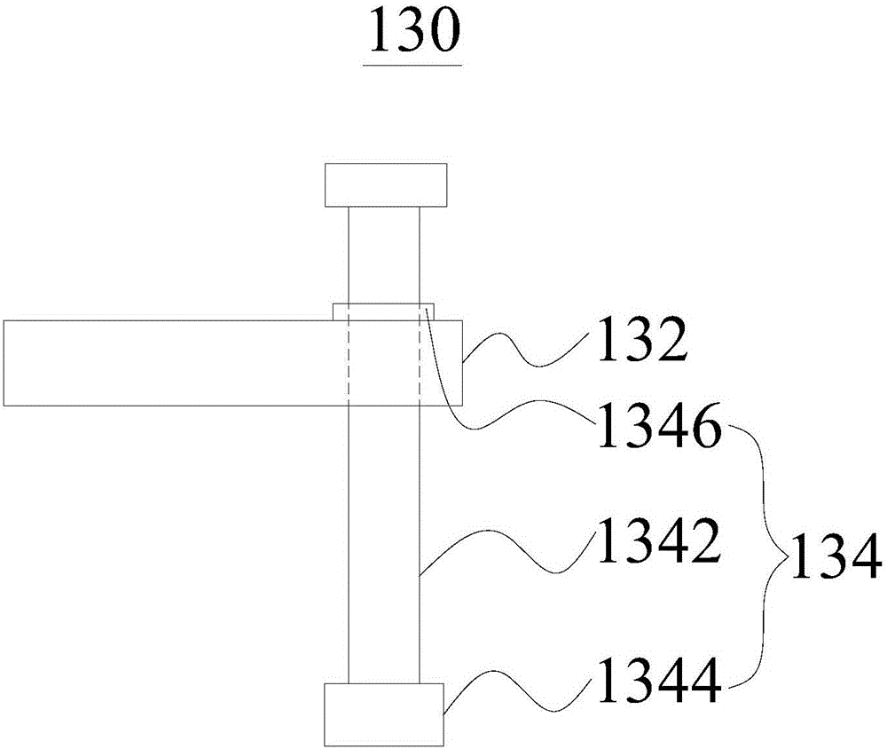
[0036] Please refer to figure 1 , the present embodiment provides a substation hanger base 100 , which includes a base body 110 , a support base 130 , a traveling wheel 140 , a ground wire 150 , a counterweight 160 , a toolbox 170 and an adjustment platform 180 .

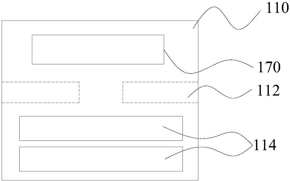
[0037] refer to figure 2, The seat body 110 is a cube made of metal material. The seat body 110 has a receiving cavity 112 . Further, the four sides of the base body 110 are provided with rectangular holes extending horizontally to the inside of the base body 110 , and the inner walls of the rectangular holes jointly define the receiving cavity 112 .

[0038] A counterweight cavity 114 for accommodating a counterweight 160 is also defined on the base body 110 . Further, a square hole extending horizontally toward the inside of the seat body 110 is opened on one side of the seat body 110 . The inner walls of the square hole collectively define a weight cavity 114 .

[0039] refer to figure 2 and image 3 , t...

Embodiment 2

[0059] Please refer to Figure 6 , this embodiment provides a substation standby hanger 200, which includes a column 210, a suspension arm 220, a hoisting mechanism 230, and the substation hanger base 100 in Embodiment 1.

[0060] The column 210 is a retractable structure. One end of the column 210 is connected to the suspension arm 220 , and the other end of the column 210 is connected to the top of the base body 110 of the substation hanger base 100 .

[0061] In this embodiment of the present invention, the column 210 includes a plurality of sub-columns, and the sub-columns are screwed to each other. Further, in this embodiment, the column 210 includes three sub-columns, namely a first sub-column 2111 , a second sub-column 2112 and a third sub-column 2113 .

[0062] The three sub-columns are in the shape of a cylinder, and the three sub-columns are nested and matched with each other, and two adjacent sub-columns are screwed. The connection situation shown here is that th...


PUM


Abstract

The invention relates to the field of building and lifting, and concretely relates to a transformer station suspension bracket pedestal and a spare transformer station suspension bracket. The transformer station suspension bracket pedestal comprises a pedestal body, a supporting seat, road wheels and an adjusting platform. The road wheels are arranged at the bottom of the pedestal body, and the pedestal body has a storage chamber. The supporting seat comprises an extension part and a supporting part, and the supporting part is arranged at one end of the extension part. The other end of the extension part is arranged in the storage chamber in a slidable manner to make the supporting part depart from or get close to the pedestal body. The supporting part is used for supporting the pedestal body in order to make the road wheels leave the ground. The adjusting platform is connected with the top surface of the pedestal body through a telescoping part. The transformer station suspension bracket pedestal is stable and reliable, and is convenient to use. The spare transformer station suspension bracket comprises a column, a suspension arm, a hoisting mechanism and the transformer station suspension bracket pedestal, one end of the column is connected with the suspension arm, the other end of the column is connected with the top part of the adjusting platform, and the hoisting mechanism is arranged at one end of the suspension arm far from the column. The column and the suspension arm are telescopic structures.

Description

technical field [0001] The invention relates to the field of construction and lifting thereof, in particular to a substation hanger base and a substation standby hanger. Background technique [0002] In the expansion or renovation project of the power station, the lifting equipment usually uses a large crane. Due to the large size of the crane, it is used in the live equipment area. The swing and lifting of the boom are limited by the site space and the surrounding live equipment. The operation is very inconvenient and there are serious accident hazards. Sometimes the power outage area has to be expanded to meet the Conditions of Use. For example, when replacing a 110kV outdoor current transformer, the current transformer is generally located behind the switch, the crane is fixed on the ground, and the lifting arm must pass through the switch to lift the transformer, and the lifting height of the lifting arm is affected by the passing line above, swinging The angle is limi...

Claims


Application Information

Patent Timeline
IPC IPC(8): B66C23/62B66C23/78B66C23/74B66C23/16B66C23/06B66C23/04
CPCB66C23/62B66C23/04B66C23/06B66C23/16B66C23/74B66C23/78
Inventor 石震李会昆解艳青陈文涛王文婷尹晓璐付玉英冯志敏
Owner DONGMING POWER SUPPLY CO STATE GRID SHANDONG ELECTRIC POWER CO
Features
  • Generate Ideas
  • Intellectual Property
  • Life Sciences
  • Materials
  • Tech Scout
  • Unparalleled Data Quality
  • Higher Quality Content
  • 60% Fewer Hallucinations
Learn More