A formwork anti-rot root compensation device

A compensating device and formwork technology, which is applied to the joints of formwork/formwork/work frame, the preparation of building components on site, construction, etc., which can solve the problems of grout leakage, labor and material waste, and insufficient cement density. Achieve the effects of improving building quality, improving work efficiency, and eliminating root rot

Active Publication Date: 2018-10-26
山东阁林板建材科技有限公司
View PDF7 Cites 0 Cited by
  • Summary
  • Abstract
  • Description
  • Claims
  • Application Information

AI Technical Summary

Problems solved by technology

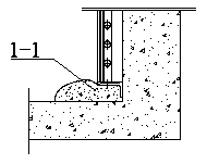
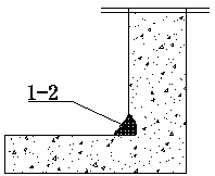
[0002] In the construction industry, the requirements for the quality of building walls are getting higher and higher, especially in the treatment of the roots of building shear walls. Since the levelness of the ground is difficult to control during pouring, the general unevenness is controlled within 15mm. The current practice is to The wall formwork (aluminum alloy) is 10mm higher than the ground, that is, if the height of the floor is 2950mm, the height of the formwork and the roof should be 2940mm, which is 10mm away from the standard height, so as to prevent the ground from being poured locally and cause the phenomenon of the roof. The floors are getting higher and higher, but after the formwork is assembled, there will be gaps 10mm~15mm lower than the structural elevation in most places. If no separate treatment is done, there will be grout leakage during pouring. The current practice is 6~8 hours before pouring , use cement mortar to manually seal, which has the following disadvantages: first, it needs to arrange special personnel to do it, resulting in a huge waste of labor and materials; second, the sealing is not strict, and the grout still leaks during pouring; third, When plugging, the inner side is not positioned, the density of the cement is not enough, and the root rot occurs after the formwork is removed, such as figure 1 Running gray part 1-1 in and figure 2 Rotten root 1-2 in the construction industry, which is the most troublesome thing in the construction industry and the most difficult thing to solve, eventually leading to the quality not meeting the requirements, so far it has not been solved

Method used


Image

  • A formwork anti-rot root compensation device
  • A formwork anti-rot root compensation device
  • A formwork anti-rot root compensation device

Examples


Embodiment Construction

[0032] In order to make the objectives, technical solutions, and advantages of the embodiments of the present invention clearer, the technical solutions in the embodiments of the present invention will be described clearly and completely in conjunction with the accompanying drawings in the embodiments of the present invention. Obviously, the described embodiments It is a part of the embodiments of the present invention, not all the embodiments. The components of the embodiments of the present invention generally described and illustrated in the drawings herein may be arranged and designed in various different configurations. Therefore, the following detailed description of the embodiments of the present invention provided in the accompanying drawings is not intended to limit the scope of the claimed invention, but merely represents selected embodiments of the present invention. Based on the embodiments of the present invention, all other embodiments obtained by those of ordinar...


PUM


Abstract

A root-rotting-preventing compensating device for a formwork is arranged on the surface of a wall and comprises the formwork, a supporting foot and a compensating plate. The cross section of the supporting foot is in an L shape, the supporting foot is fixedly mounted on the bottom face of the formwork through positioning bolts, and the compensating plate is perpendicularly arranged on the outer side face of the supporting foot and located between the supporting foot and the wall. The compensating plate is connected with the supporting foot through step bolts penetrating through square holes in the compensating plate, the supporting foot is provided with a long groove corresponding to the square holes, each step bolt is provided with a pressure spring, and a retracting positioning spring is arranged between each positioning bolt and the corresponding step bolt. By means of the root-rotting-preventing compensating device for the formwork, the phenomenon that lime leaks from the bottom of the inner wall and consequently root rotting occurs is effectively solved, the building quality is improved, the investment of labor and material resources in construction is reduced, the cost is lowered, and work efficiency is improved.

Description

Technical field [0001] The invention relates to the field of construction technology, in particular to a formwork anti-rot root compensation device. Background technique [0002] In the construction industry, the requirements for the quality of the walls of buildings are getting higher and higher, especially in the treatment of the roots of the building shear walls. Because the levelness of the ground is difficult to control when pouring the ground, the general height and unevenness are controlled within 15mm. The current practice is internal The wall template (aluminum alloy) is 10mm higher than the ground, that is, if the floor height is 2950mm, the height of the template and the top plate is set to 2940mm, and the height difference is 10mm from the standard to prevent the partial height of the ground from being poured, causing the phenomenon of the roof. The higher the floor is, the higher the floor is, but after the mold is assembled, there will be gaps 10mm~15mm lower than t...

Claims


Application Information

Patent Timeline
Patent Type & Authority Patents(China)
IPC IPC(8): E04G17/00
CPCE04G17/005
Inventor 朱德玉沈冲张微刘峰李兴党朱德强满建鑫满爱莲张勇张智勇
Owner 山东阁林板建材科技有限公司
Why Eureka
Try Eureka