Lubricating oil recycling device of automobile gearbox

A cyclic regeneration and gearbox technology, applied in the field of auto parts, can solve problems such as uneven cooling, gear damage, bearing damage, etc., to avoid the effect of impurities remaining

Inactive Publication Date: 2017-03-22
高安市超鹰科技有限公司
View PDF13 Cites 3 Cited by
  • Summary
  • Abstract
  • Description
  • Claims
  • Application Information

AI Technical Summary

Problems solved by technology

This invention retains the original gear splash lubrication, and adds an oil receiving box on the gear rib plate, and an oil scraper on the bearing side, so as to ensure that the lubricating oil can fully enter the bearing, and increase the lubrication oil supply of the bearing, which fundamentally solves the problem of The speed of the reducer is low, and the lubricating oil cannot reach the bearing part, causing the bearing to be damaged; however, since the device does not involve lubricating oil regeneration, the lubricating oil is recycled in the oil pool, causing impurities to repeatedly stick to the gear, resulting in gear damage. Only frequent replacement of lubricating oil can ensure the stability of its work, and there is a phenomenon of uneven cooling

Method used


Image

  • Lubricating oil recycling device of automobile gearbox
  • Lubricating oil recycling device of automobile gearbox
  • Lubricating oil recycling device of automobile gearbox

Examples


Embodiment 1

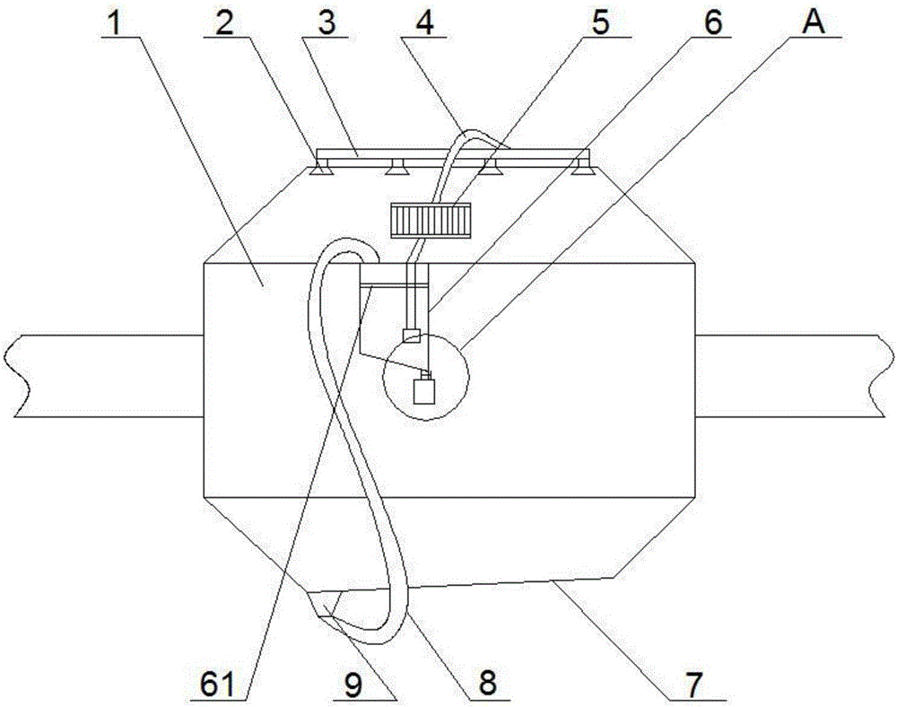
[0029] An automotive gearbox lubricating oil circulation regeneration device, comprising a gearbox body 1, a spray mechanism arranged on the upper part of the gearbox body 1, a circulation outlet 9 arranged at the bottom of the gearbox body 1, and connected to the circulation outlet 9 and the filter mechanism 6 of the spray mechanism;

[0030] The spray mechanism includes a spray pipe 3 arranged on the upper part of the gearbox body 1, and

[0031] One end penetrates the upper part of the gearbox body 1 and extends into the gearbox body 1, and the other end communicates with the spray nozzle 2 of the spray pipe 3;

[0032] The bottom surface of the gear case 1 is an inclined surface 7, and the circulation outlet 9 is provided at the low-lying end of the inclined surface 7;

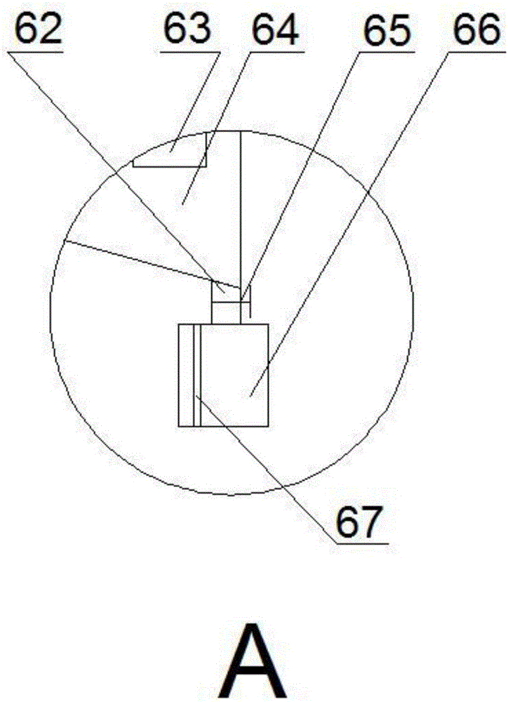
[0033] The filter mechanism includes a filter chamber 64, an oil inlet pipe 8 and an oil outlet pipe 4 arranged on the filter chamber 64, an oil pump 63 arranged at the end of the oil outlet pipe 4, and t...

Embodiment 2

[0037] The difference from Embodiment 1 is that the bottom surface of the filter cavity 64 is an inclined bottom surface, and the deposition tube 62 is arranged at the lower end of the inclined bottom surface.

[0038] A transparent display column 67 for observing the internal state of the deposition tank 66 is arranged in the deposition tank 66 .

[0039]The filtering bottom surface adopted in this embodiment is an inclined bottom surface, and the sedimentation tube is arranged at the low-lying end of the inclined bottom surface, and can also be arranged in a funnel shape, and is used in the sedimentation tank to observe the transparent display column of the internal state of the sedimentation tank, which can be used in the sedimentation tank. The real-time situation of lubricating oil can be visually observed during daily inspections. Since the gears in the gearbox will generate a lot of heat due to high-load operation, if it is not dissipated in time, it will cause accelerat...

Embodiment 3

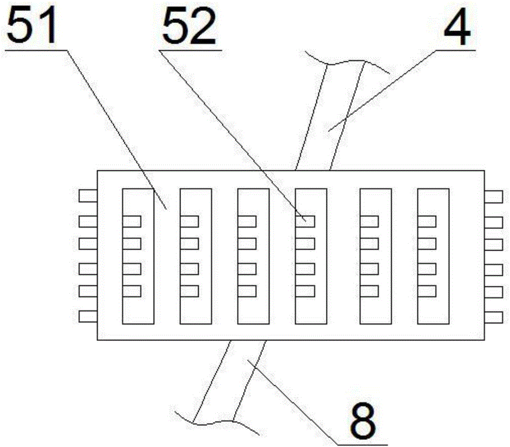
[0041] The difference between it and the second embodiment is that: the oil outlet pipe 4 is provided with a cooling mechanism 5 for cooling lubricating oil; Sheet 52.

[0042] The upper opening of the deposition tank 66 is provided with an internal thread, and the lower part of the deposition tube 62 is provided with an external thread matched therewith, and the surfaces of the internal thread and the external thread are provided with a polytetrafluoroethylene coating for sealing.

[0043] The transparent display column 67 is semi-cylindrical.

[0044] The upper part of the filter cavity 64 is provided with a filter screen 61 for filtering lubricating oil entering the filter cavity.

[0045] The working method of the present invention: through the oil pump, the lubricating oil in the filter cavity is sucked out and sent to the cooling mechanism, and after passing through the cooling mechanism, it enters the spraying mechanism to spray the gear box, and the lubricating oil at...


PUM


Abstract

The invention provides a lubricating oil recycling device of an automobile gearbox. The lubricating oil recycling device comprises a gearbox body, a spraying mechanism, a circulating outlet and a filtering mechanism, wherein the spraying mechanism is arranged on the upper part of the gearbox body, the circulating outlet is formed in the lower part of the gearbox body, and the filtering mechanism is connected with the circulating outlet and the spraying mechanism. According to the lubricating oil recycling device, lubricating oil in the gearbox body is filtered and circulated, so that impurities in the lubricating oil are filtered, the lubricating oil is cooled, constant damage to a gear due to turbidity of the lubricating oil is effectively avoided, and heat on the gear can be removed in time, so that the gear is kept in an optimal operating state all the time, the service cycle of the lubricating oil at a time is extended, and the service life of the gearbox is prolonged.

Description

technical field [0001] The invention relates to the technical field of auto parts, in particular to a lubricating oil circulation regeneration device for an auto gearbox. Background technique [0002] Common gearbox lubrication is mostly lubricated by oil pool or smearing lubricating grease, but this structure will produce some impurities during the meshing process between the gears, so it is necessary to replace the differential after a period of time The lubricating oil in the gear box and the gear box, and during high-load operation, a certain amount of heat will be generated due to the meshing between the gears. The heat is naturally cooled by the gears, and the heat is taken away by the cooling oil. However, the conventional The method will cause the lubricating oil to circulate in the box, and the impurities will also stick to the gears, resulting in crushing during the meshing process. [0003] The application number is 201520672833.2, which discloses a device fo...

Claims


Application Information

Patent Timeline
IPC IPC(8): F16H57/04
CPCF16H57/0404F16H57/0413F16H57/0415
Inventor 吴英
Owner 高安市超鹰科技有限公司
Why Eureka
Try Eureka