Control system for lifting lamp base

A control system and lamp holder technology, which is applied to the components of lighting devices, lighting devices, lighting auxiliary devices, etc., can solve the problems of increased wiring costs, lowering of lamp holders, hidden safety hazards, etc., saving time and effort, reducing Labor and cost saving effects

Active Publication Date: 2017-03-22
GUANGXI COLLEGE OF WATER RESOURCES & ELECTRIC POWER
View PDF11 Cites 1 Cited by
  • Summary
  • Abstract
  • Description
  • Claims
  • Application Information

AI Technical Summary

Problems solved by technology

[0003] At present, the control of some liftable lamp holders is realized by adding several lift, drop, and stop control switches and increasing the corresponding control circuit wiring. When the distance is long, the wiring cost will be greatly increased, and multiple switches are easy to be misoperated; another solution is to use a switch to determine whether to enter the lifting lamp holder mode by detecting whether the bulb is good or bad. When the bulb is good, the switch is used for the bulb On and off control, when the bulb is broken, it will enter the lifting lamp holder mode. When the bulb is good, the lamp holder cannot be lowered when you want to change a bulb of other wattage, and the bulb is broken and cannot be replaced in time. There are children who are playful and keep pressing the switch to raise and lower the lamp holder, causing safety hazards

Method used


Image

  • Control system for lifting lamp base
  • Control system for lifting lamp base
  • Control system for lifting lamp base

Examples


Embodiment Construction

[0021] The technical solutions in the embodiments of the present invention will be further described below in conjunction with the accompanying drawings in the examples of the present invention.

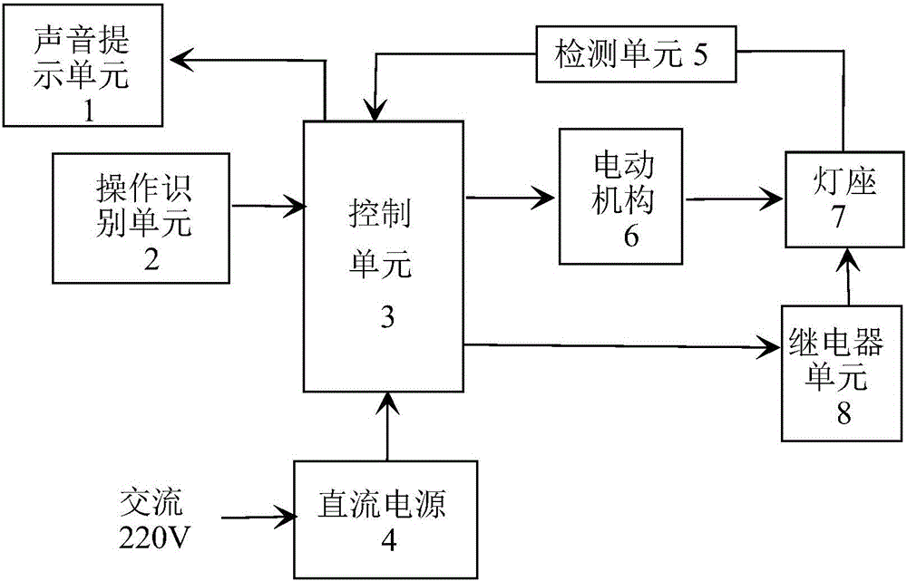
[0022] Such as figure 1 Shown: a liftable lamp holder control system, the system is composed of voice prompt unit 1, operation recognition unit 2, control unit 3, DC power supply 4, detection unit 5, motor mechanism 6, lamp holder 7, relay unit 8.

[0023] The DC power supply 4 utilizes 220V AC power to obtain +5V DC power through rectification, voltage stabilization and other links, and provides the DC power required for the entire circuit to work.

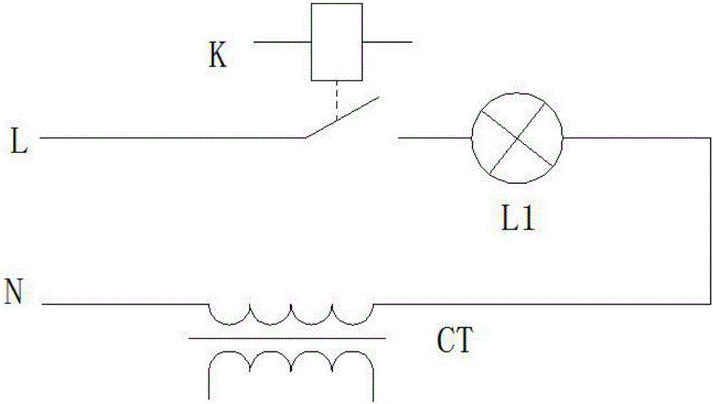
[0024] The detection unit 5 is composed of a current transformer and an amplifier circuit. The primary side of the current transformer is connected in series with the light bulb. When the current flows, the secondary side has a current output, which is amplified by the amplifier and sent to the intelligent control unit 3 for judgment. ...


PUM


Abstract

The invention discloses a control system for a lifting lamp base. The control system is composed of a direct-current power source, a control unit, a sound prompting unit, a detecting unit, a power-driven mechanism, the lamp base and a relay unit. The control system is characterized by further comprising an operation recognition unit; and the operation recognition unit coverts collected analog voltage into a digital value and transmits the digital value to the control unit for change-over switch mode judgment. The operation recognition unit is formed by a switch S1, a conversion button K1, a resistor R1, a resistor R2 and an A/D convertor, and either the switch S1 is in the normal switching mode or the lamp base lifting mode is controlled by operating the small conversion button K1. According to the control system, operation of multiple functions of the lamp base can be achieved through one switch; the operation recognition unit is used for achieving switching between the normal switching mode and the lamp base lifting mode, and therefore error operation by children is effectively prevented; and meanwhile, additional wiring is not needed, and therefore cost is saved. The operative difficulty of lamp replacement is reduced, and the lamp base can be descended by operating the switch to be replaced.

Description

technical field [0001] The invention belongs to the technical field of building lighting, and relates to a novel intelligent lamp holder capable of lifting and lowering and a control method. Background technique [0002] At present, when a bulb is broken and replaced, it is often necessary to climb up with the help of a ladder or a shelf. Replacing light bulbs is a simple process, but due to height restrictions, this simple process has become extremely challenging. For maintenance personnel, it is full of safety hazards when working at heights, and it is time-consuming and laborious to move ladders or shelves. Especially high-altitude places such as gymnasiums and halls. [0003] At present, the control of some liftable lamp holders is realized by adding several lift, drop, and stop control switches and increasing the corresponding control circuit wiring. When the distance is long, the wiring cost will be greatly increased, and multiple switches are easy to misuse; another...

Claims


Application Information

Patent Timeline
Patent Type & Authority Applications(China)
IPC IPC(8): F21V23/00F21V21/38F21V23/04
CPCF21V21/38F21V23/003F21V23/04Y02B20/40
Inventor 彭情潘元忠杨丽梅杨业博谢基用肖福楠林炳奎陈润波卢晓强廖广凤陈思宇
Owner GUANGXI COLLEGE OF WATER RESOURCES & ELECTRIC POWER
Why Eureka
Try Eureka