Wave finned heat exchanger and manufacturing method thereof

A manufacturing method and heat exchanger technology, which are applied in the direction of heat exchanger types, heat exchanger shells, indirect heat exchangers, etc. Problems such as low bonding strength and thermal conductivity

Inactive Publication Date: 2017-03-22
谢彦君
View PDF6 Cites 7 Cited by
  • Summary
  • Abstract
  • Description
  • Claims
  • Application Information

AI Technical Summary

Problems solved by technology

This makes it difficult for the thermally conductive adhesive to reach near the centerline of the flat tube, resulting in lower overall bonding strength and thermal conductivity of the microchannel heat exchanger

Method used


Image

  • Wave finned heat exchanger and manufacturing method thereof
  • Wave finned heat exchanger and manufacturing method thereof
  • Wave finned heat exchanger and manufacturing method thereof

Examples


Embodiment 1

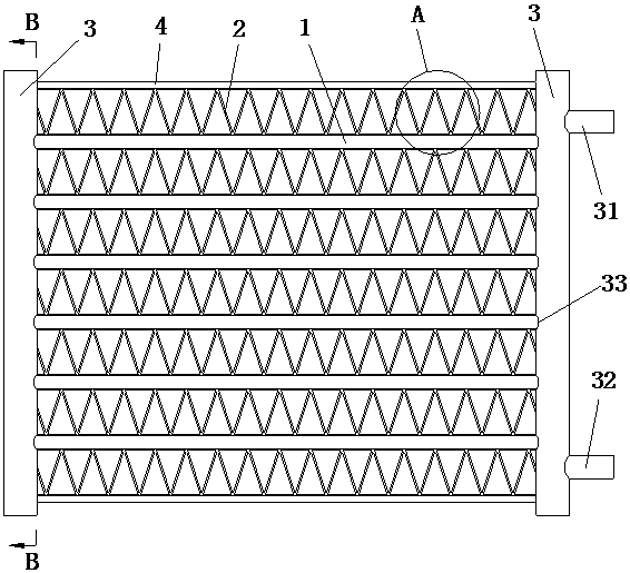
[0092] Such as figure 1 As shown, the flat tube-fin heat exchanger provided in this embodiment includes: several flat tubes 1, several fins 2 (or fin strips), two liquid collection chambers (or liquid collection pipes, or header) 3. Preferably, two outer side panels 4 are also included. Wherein, the flat tube 1, the fins 2, and the metal parts of the liquid collecting chamber 3 are all made of a single-layer aluminum alloy material. Abandoning the expensive aluminum alloy material of the solder composite layer in the prior art makes the manufacturing cost of the flat-tube-fin heat exchanger lower, for example, the cost of raw materials can be reduced by 30% to 40%.

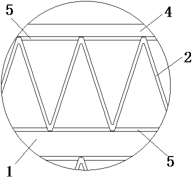
[0093] Specifically, the flat tubes 1 and the fins 2 are sequentially arranged at intervals, and the flat tubes 1 and the fins 2 are bonded by a first adhesive layer 5 . The flat tube 1 includes a single-hole mouth-shaped tube, a B-shaped folded tube, an extruded porous harmonica-shaped tube, and the like. In ...

Embodiment 2

[0120] In this embodiment, the same reference numerals are assigned to the same parts as in the first embodiment, and the same text descriptions are omitted.

[0121] Such as Figure 1 to Figure 3 As shown, the first adhesive layer 5 is made of a mixture of an adhesive substrate and conductive and thermally conductive fillers, wherein the conductive and thermally conductive filler accounts for 20% to 30% by weight of the first adhesive layer 5 .

[0122] As a preferred technical solution, the conductive and thermally conductive filler is graphite powder or metal powder. Specifically, the conductive and thermally conductive fillers are formed by mixing graphite powders of different particle sizes. Of course, the conductive and thermally conductive fillers can also be formed by mixing metal powders of different particle sizes. Of course, the conductive and thermally conductive fillers are more likely to be formed by mixing graphite powder and Metal powders of different particle...

Embodiment 3

[0126] In this embodiment, the same reference numerals are assigned to the same parts as in the first embodiment, and the same text descriptions are omitted.

[0127] In this embodiment, the manufacturing method of the flat tube-fin heat exchanger is carried out in the following steps:

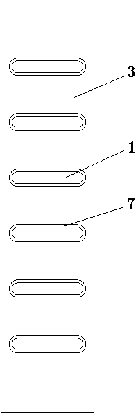
[0128] Step 1. Set a second adhesive layer on the outer surface of both ends of the flat tube or at the slot hole of the liquid collection chamber, insert the two ends of each flat tube into the corresponding slot hole, and apply the second adhesive The flat tube and the slot hole of the liquid collection chamber are bonded and solidified to form a flat pipe liquid collection chamber assembly;

[0129] Step 2, setting a first adhesive layer on the outer surface of the joint between the flat tube and the fin or at the crest of the fin;

[0130] Step 3. Fins are placed between two adjacent flat tubes, and the flat tubes and fins are bonded and solidified by the first adhesive layer to form a fl...


PUM


Abstract

The invention discloses a heat exchanger and a manufacturing method thereof. The heat exchanger is characterized by comprising flat tubes, fins and liquid collection cavities, wherein the flat tubes and the fins are alternately arranged, and in addition, each flat tube is adhered to the corresponding fin through a first adhesive layer; the side wall of each liquid collection cavity is provided with a plurality of sequentially arranged slot holes; the two ends of each flat tube are inserted into the corresponding slot holes respectively; the end parts of each flat tube are adhered to the corresponding slot holes by second adhesive layers in a sealing manner respectively; or the liquid collection cavities are formed by stacking the ends of the flat tubes; and in addition, the ends of two adjacent flat tubes are adhered to each other by the corresponding second adhesive layer in the sealing manner. According to the heat exchanger, the adhesion effects between each flat tube and the corresponding fin as well as between each flat tube and the corresponding liquid collection cavity are both stable and firm, the sealing strength between each flat tube and the corresponding liquid collection cavity is fully guaranteed, and the heat exchange performance of the heat exchanger can also be greatly improved.

Description

[0001] The patent application for the present invention is a divisional application. The application number of the original application is CN201610401711.9, the application date is June 11, 2016, and the name of the invention is: corrugated fin heat exchanger and its manufacturing method. technical field [0002] The invention relates to a heat exchanger, in particular to a flat tube and corrugated fin heat exchanger completely connected by adhesive and a manufacturing method thereof. Background technique [0003] Heat exchangers are heat exchange equipment widely used in vehicles, communication equipment, air conditioners and other products. Existing heat exchangers (such as flat tube-fin heat exchangers) are usually composed of flat tubes, fins, and headers, and, in the traditional manufacturing method of flat tube-fin heat exchangers, flat tubes It is welded and formed by brazing between the fins and between the flat tube and the collector. However, this welding method ...

Claims


Application Information

Patent Timeline
Patent Type & Authority Applications(China)
IPC IPC(8): F28D1/053F28F1/32F28F9/16F28F21/08
CPCF28D1/05316F28F1/32F28F9/162F28F11/00F28F21/081F28F2275/04
Inventor 不公告发明人
Owner 谢彦君
Why Eureka
Try Eureka