Air flow measurement device
A flow measurement device and air duct technology, which is applied in the direction of detecting fluid flow by measuring pressure difference, volume/mass flow generated by mechanical effects, etc., can solve problems such as not being able to meet the requirements of automatic control, so as to save verification costs and improve flow capacity , good repeatability and long-term stability
- Summary
- Abstract
- Description
- Claims
- Application Information
AI Technical Summary
Problems solved by technology
Method used
Image

Examples
Embodiment 1
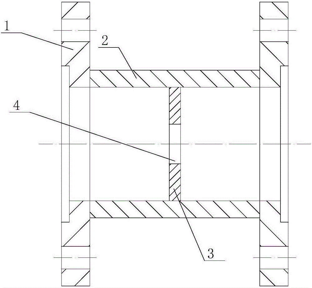
[0038] figure 1 It is the front view of the air duct flow measuring device of Embodiment 1 of the present invention; figure 2 yes figure 1 left view of .
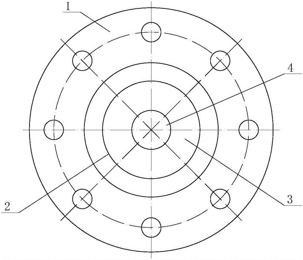
[0039] The meanings of the newly appearing reference signs in the figure are as follows: 1. Mounting flange; 2. Pipe wall; 3. Orifice plate; 4. Main hole.
[0040] An air duct flow measurement device, including a pipe wall, the two ends of the pipe wall are respectively fixedly connected with the installation flange, the installation flange is used to cooperate with the flange of the pipe, the measuring device is installed in the pipeline, and the pipe wall An orifice plate is fixedly installed, the orifice plate is perpendicular to the axial direction of the pipe wall, the center of the orifice plate is perpendicular to the axis of the pipe wall, and a main hole is arranged at the center of the orifice plate, and the main hole is circular.
[0041] The ingenious design of the rectified porous flowmeter lies in the comb...
Embodiment 2
[0047] image 3It is a left side view of the air duct flow measuring device according to Embodiment 2 of the present invention. In the figure, the same reference numerals as those used in the above-mentioned embodiments still follow the definition of the reference numerals in the above-mentioned embodiments. The meanings represented by the newly appearing reference signs in the figure are as follows: 5, satellite holes.
[0048] The difference between this embodiment and embodiment 1 is:
[0049] The outer side of the main hole is also provided with satellite holes, and the satellite holes are evenly distributed along the outer side of the main hole.
[0050] By arranging the satellite holes, the flow area of the fluid can be increased, the flow capacity can be improved, and the loss caused by the measuring device to the pressure can be reduced. The permanent pressure loss of the porous orifice plate can be reduced to 1 / 2 of that of the single-hole orifice plate, which gr...
Embodiment 3
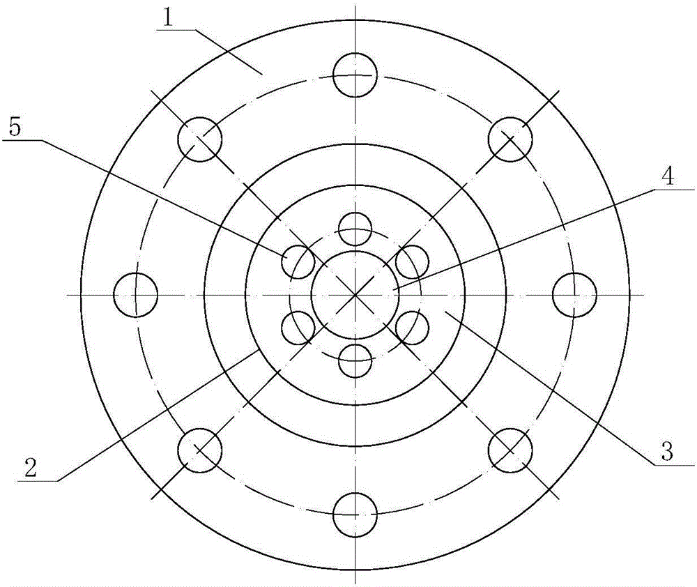
[0062] Figure 4 is a cross-sectional view of the air duct flow measuring device of Embodiment 3 of the present invention; Figure 5 yes Figure 4 left view of . In the figure, the same reference numerals as those used in the above-mentioned embodiments still follow the definition of the reference numerals in the above-mentioned embodiments. The implication represented by the newly appearing reference numeral among the figure is as follows: 6, fairing cover.
[0063] The difference between this embodiment and embodiment 2 is:
[0064] The orifice plate is provided with a shroud in the area between the main hole and two adjacent satellite holes, and the shroud is hemispherical.
[0065] When the air flow enters the measuring device from the left side in the figure, and encounters the hemispherical shroud, it can be guided by the shroud first, and smoothly flows into the satellite hole 5 and the main hole 4, avoiding direct impact on the holes The vortex and turbulence form...
PUM
 Abstract
Description
Claims
Application Information
 - R&D
- Intellectual Property
- Life Sciences
- Materials
- Tech Scout
- Unparalleled Data Quality
- Higher Quality Content
- 60% Fewer Hallucinations
Browse by: Latest US Patents, China's latest patents, Technical Efficacy Thesaurus, Application Domain, Technology Topic, Popular Technical Reports.
© 2025 PatSnap. All rights reserved.Legal|Privacy policy|Modern Slavery Act Transparency Statement|Sitemap|About US| Contact US: help@patsnap.com