Motor performance testing system

A technology for testing systems and performance, applied in the direction of motor generator testing, measuring devices, instruments, etc., can solve problems such as unrealizable, low accuracy of speed sensor, lack of inertial load adjustment, etc., to achieve the effect of expanding the application range and ensuring reliability

Active Publication Date: 2017-03-22
WUHAN HUAZHONG NUMERICAL CONTROL
View PDF10 Cites 13 Cited by
  • Summary
  • Abstract
  • Description
  • Claims
  • Application Information

AI Technical Summary

Problems solved by technology

[0002] At present, the motor performance testing devices on the market generally have torque and speed signal detection and voltage and current signal detection. Among them, the accuracy of the speed sensor is very low, and it cannot be used for dynamic performance analysis of speed changes.
If you want to add a high-precision speed detection device, it cannot be realized because the loading device is installed at the end; the loading of the dynamometer can only be adjusted by resistive load. For inertial loads, you can only rely on couplings, connecting rods and fixed Inertia flywheel, etc., the inertial loads of these links are fixed when the design of the dynamometer is completed.
The motor performance test device needs to have the ability to simulate various on-site working conditions. The original design can only adjust the resistive load, but lacks the adjustment of the inertial load, which greatly reduces the application range and test validity of the test device.
The above two technical difficulties limit the development of motor performance testing devices

Method used


Image

  • Motor performance testing system
  • Motor performance testing system
  • Motor performance testing system

Examples


Embodiment Construction

[0019] In order to more clearly illustrate the purpose, technical solutions and advantages of the present invention, the present invention will be further described in detail below in conjunction with the accompanying drawings and embodiments. It should be understood that the specific embodiments described here are only used to explain the present invention, not to limit the present invention. In addition, the technical features involved in the various embodiments of the present invention described below may be combined with each other as long as there is no conflict with each other.

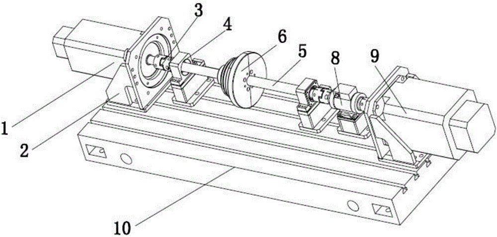
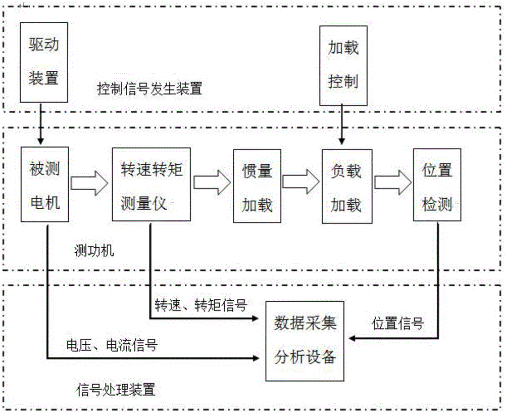
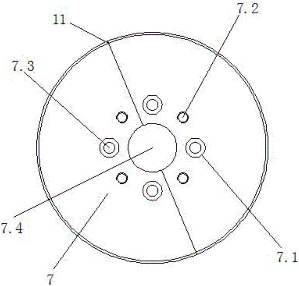
[0020] Such as Figures 1 to 3 As shown, the present embodiment provides a motor performance testing system, including a driving device 12, a motor to be tested 1, a loading control device 13 (in this embodiment, a stabilized power supply with adjustable output is selected), a loading device 9 and data acquisition and analysis Equipment 14, the drive device 12 is electrically connected to the m...


PUM


Abstract

The invention discloses a motor performance testing system which comprises a driving device, a motor to be tested, a loading control device, loading equipment, and data acquisition and analysis equipment. The driving device is electrically connected to the motor to be tested. The output shaft of the motor to be tested is axially connected to one end of a transmission shaft through a coupler. The other end of the transmission shaft is connected to the loading equipment through a transmission gear set. The loading equipment is electrically connected to the loading control device. The coupler is equipped with a torque rotation speed sensor. The transmission shaft is equipped with a combined inertia plate group for adjusting an inertia load. A position sensor is arranged between the transmission gear set and the loading equipment. The data acquisition and analysis equipment is connected to the motor to be tested, the torque rotation speed sensor and the position sensor. According to the motor performance testing system, the high precision position detection can be provided, at the same time the inertia load can be adjusted, the simulation of various working conditions is facilitated, and the system is especially suitable for the motor tests of all working conditions.

Description

technical field [0001] The invention relates to a motor performance test system, in particular to a motor performance test system with an adjustable inertia loading function and a high-precision position detection function. Background technique [0002] At present, the motor performance testing devices on the market generally have torque and speed signal detection and voltage and current signal detection. The accuracy of the speed sensor is very low, and it cannot be used for dynamic performance analysis of speed changes. If you want to add a high-precision speed detection device, it cannot be realized because the loading device is installed at the end; the loading of the dynamometer can only be adjusted by resistive load. For inertial loads, you can only rely on couplings, connecting rods and fixed Inertia flywheel, etc., the inertial loads of these links are fixed when the design of the dynamometer is completed. The motor performance test device needs to have the ability ...

Claims


Application Information

Patent Timeline
Patent Type & Authority Applications(China)
IPC IPC(8): G01R31/34G01D21/02
CPCG01D21/02G01R31/34
Inventor 张华锋曹本文吴慧高杰翟世欣
Owner WUHAN HUAZHONG NUMERICAL CONTROL
Why Eureka
Try Eureka