
Ultrasonic ghost imaging method and device based on principle of calorescence ghost imaging

An ultrasonic and ghost imaging technology, applied in the field of target imaging detection, can solve the problems of destroying the authenticity of the acoustic image, poor imaging quality, and low imaging resolution, and achieve good anti-disturbance characteristics, high-quality imaging, and high imaging quality Effect

Inactive Publication Date: 2017-03-22
XI AN JIAOTONG UNIV
View PDF1 Cites 13 Cited by
  • Summary
  • Abstract
  • Description
  • Claims
  • Application Information

AI Technical Summary

Problems solved by technology

The problem with the above-mentioned traditional medical ultrasound imaging technology is that the small structures in human organs scatter the incident ultrasound, causing part of the energy of the incident ultrasound to scatter in various spatial directions, and the energy returned to the ultrasound probe is too low to form a clear human body. Tissue and organ images; ultrasound artifacts due to reverberation effects, mirror effects, rear wall enhancement effects, side lobe effects, and partial volume effects destroy the authenticity of sonographic images and reduce the credibility of images, Inconvenience or even misdiagnosis for doctors in map recognition and disease diagnosis
[0005] However, the existing traditional medical ultrasound imaging is susceptible to interference, low imaging resolution, poor imaging quality, and traditional sonar detection technology can only detect the presence or absence of underwater target objects and cannot form a clear image of the target object

Method used


Image

  • Ultrasonic ghost imaging method and device based on principle of calorescence ghost imaging
  • Ultrasonic ghost imaging method and device based on principle of calorescence ghost imaging
  • Ultrasonic ghost imaging method and device based on principle of calorescence ghost imaging

Examples


Embodiment Construction

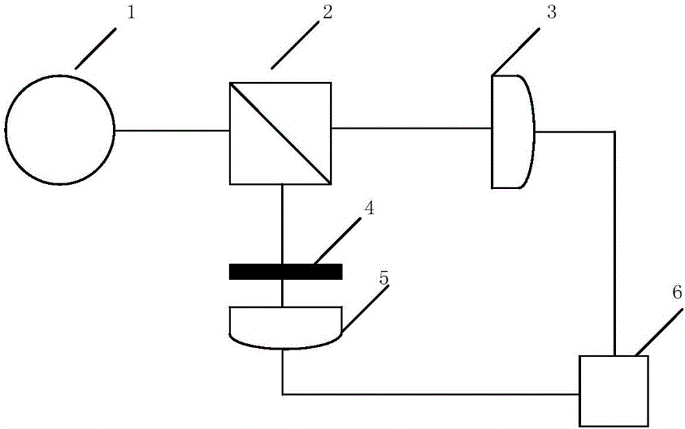
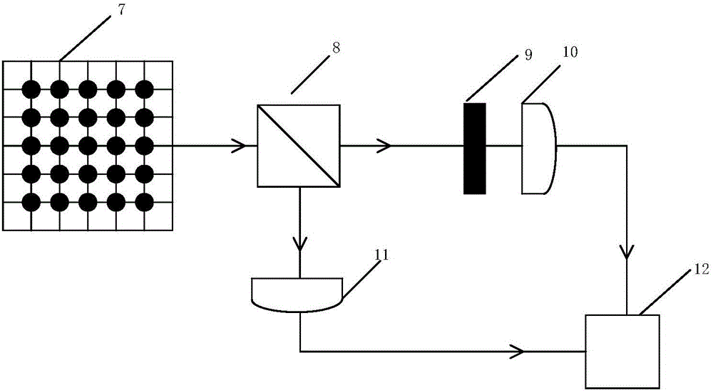
[0034] The present invention will be further described below in conjunction with the accompanying drawings, but the protection scope of the present invention should not be limited thereby. The basic idea of ​​the invention is to introduce ultrasonic wave as a wave source into ghost imaging, and realize a new ultrasonic ghost imaging method.

[0035] The invention fully considers the advantages of ghost imaging that can realize lensless imaging, high imaging resolution, and stronger anti-disturbance ability than traditional imaging technology, and proposes an ultrasonic ghost imaging method that uses ultrasound as a wave source and combines the principle of dual-channel ghost imaging. . The method can realize the imaging of the target object, and can realize high-resolution imaging no matter for short-distance imaging or long-distance imaging, and has strong anti-disturbance ability.

[0036] Optical ghost imaging is achieved by the coincidence measurement of signals from two ...


PUM


Abstract

The invention provides an ultrasonic ghost imaging method and device based on the principle of lens-free calorescence ghost imaging, which belongs to the field of target imaging detection. Ultrasonic wave emitted by an ultrasonic emission source is divided into two beams through an acoustic beam splitter. The ultrasonic wave transmitted through an object to be imaged is received by an ultrasonic wave barrel detector. An ultrasonic CCD detector is used to receive an ultrasonic beam emitted by the ultrasonic emission source. A correlator is used to calculate the second order correlation function of the ultrasonic sound intensity detected by two ultrasonic detectors. Coincidence measurement is carried out on two ultrasonic signals to acquire the image of the object to be imaged. According to the invention, the ultrasonic wave is introduced into ghost imaging as a wave source; a new ultrasonic ghost imaging method is realized; the imaging method has a great anti-perturbation characteristic; and compared with traditional ultrasonic imaging, the imaging method can realize lensless imaging, and has the advantages of high resolution, high image quality and the like.

Description

technical field [0001] The invention belongs to the field of target imaging detection, relates to imaging an object by using the principle of ghost imaging, and in particular relates to an ultrasonic ghost imaging method and device based on the principle of thermal-light ghost imaging. Background technique [0002] Since the discovery of X-rays by German physicist Wilhelm Konrad Roentgen in 1895 paved the way for medical imaging technology, medical ultrasound imaging, computerized tomography, magnetic resonance imaging, digital subtraction angiography and emission Medical imaging technologies such as tomography have gradually emerged and matured. Among them, medical ultrasound imaging has been applied to the heart, great blood vessels and the Display and measurement of the gallbladder. Traditional medical ultrasound imaging is to use piezoelectric materials with piezoelectric effect to make ultrasound probes to realize the conversion of voltage and acoustic vibration. Acc...

Claims


Application Information

Patent Timeline
IPC IPC(8): G01S15/89
CPCG01S15/89
Inventor 刘建彬王婧婧韩奇徐卓
Owner XI AN JIAOTONG UNIV
Learn More