Optical scanner controller support

An optical scanner and controller technology, applied in the direction of using feedback control, etc., can solve the problems that there is no optical scanner control device bracket, no relevant literature or patent disclosure, etc., to achieve accurate accuracy, improve work efficiency, Simple to use effects

Inactive Publication Date: 2017-03-22
赛维航电科技有限公司
View PDF6 Cites 2 Cited by
  • Summary
  • Abstract
  • Description
  • Claims
  • Application Information

AI Technical Summary

Problems solved by technology

At present, there is no such bracket specially applied to the optical scanner control device, and there is no related literature or patent publication

Method used


Image

  • Optical scanner controller support
  • Optical scanner controller support
  • Optical scanner controller support

Examples


Embodiment Construction

[0029] In order to make the object, technical solution and advantages of the present invention more clear, the present invention will be further described in detail below in conjunction with the examples. It should be understood that the specific embodiments described here are only used to explain the present invention, not to limit the present invention.

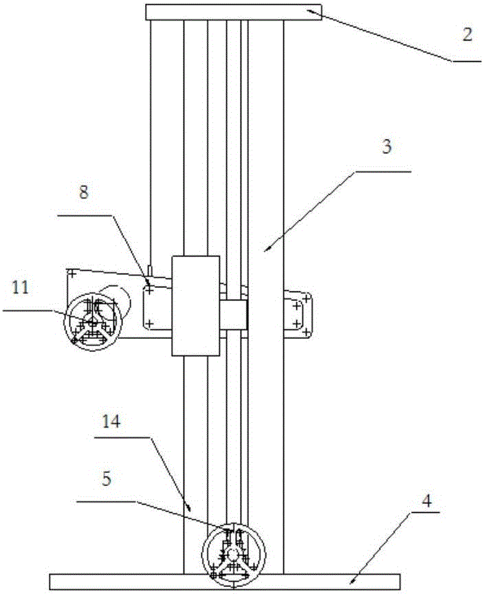
[0030] figure 1 It is a schematic diagram of the structure of the optical scanner controller bracket. The combined performance index is to select the main components, including the gantry 1 formed by two vertically parallel pipes 3 arranged on both sides of the beam 2 and the base 4, the lifting mechanism and the pitching mechanism.

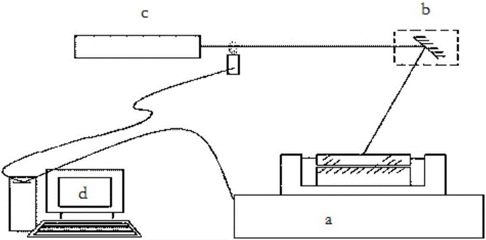
[0031] figure 2 It is a schematic diagram of the structure of the bracket of the present invention for the composition of the holographic exposure light path, the optical scanner control device bracket a and the laser platform, the optical scanner holographic automatic exposure device, the ...


PUM


Abstract

The invention relates to an optical scanner controller support comprising: a lifting device comprising a base and slide bars mounted in parallel on both sides of the base, wherein a lead screw is arranged in parallel to the slide bar at one side and is connected with a lifting assembly, and two parallel lifting plates are arranged on the slide bar at one side and the slide bar and lead screw on the other side; a pitching device including a bracket connected to the lifting plates on both sides through shafts, wherein a pitching assembly is installed on a lifting plate on one side, the lead screw drives the lifting plates and the bracket connected to the lifting plates to slide up and down along the slide bars, and the pitching assembly is connected to a gear structure by the bracket and the rotation of the bracket is driven by rotating the pitching assembly; and a counterweight device including a counterweight steel rope connected with the lifting plates on both sides, wherein the other end of the counterweight steel rope is connected with a balancing weight as heavy as a lifted object. The optical scanner controller support can realize the change of the height of an optical scanner to a work surface and the emergent light angle of the optical scanner by the movement of the mechanical structure.

Description

technical field [0001] The invention relates to the technical field of mechanical control systems, in particular to an optical scanner controller bracket with the function of controlling the scanning of light beams. Background technique [0002] In control systems such as turntables, brackets, and antenna controls, precision angle measurement is a prerequisite for precise position control. As a device for detecting mechanical rotation angle and displacement, the bracket controller has the advantages of high measurement accuracy, stable and reliable operation, etc. At the same time, since there is no electromagnetic induction, friction, etc., the service life can be almost infinitely long, and there is no special requirement for ambient temperature, humidity, oil pollution, etc., so it is widely used in aviation, aerospace, military and industrial production. [0003] The role of the optical scanner control device is to form an optical scanning system with the optical scanne...

Claims


Application Information

Patent Timeline
Patent Type & Authority Applications(China)
IPC IPC(8): G05D3/12
CPCG05D3/12
Inventor 陈伟武毅陈未希
Owner 赛维航电科技有限公司
Why Eureka
Try Eureka