
Spent fuel transfer channel shielding device

A channel shielding and spent fuel technology, which is applied in shielding, nuclear power generation, climate sustainability, etc., can solve the problems of high dose rate around the fuel transfer channel, hinder the relative movement of the shielding body, and fail to meet the shielding requirements, etc., to achieve convenient construction , simple structure, and the effect of reducing maintenance costs

Active Publication Date: 2017-03-22
CHINA NUCLEAR POWER ENG CO LTD
View PDF7 Cites 7 Cited by
  • Summary
  • Abstract
  • Description
  • Claims
  • Application Information

AI Technical Summary

Problems solved by technology

Expansion joints must be reserved because they are used to buffer the relative movement between buildings. At the same time, due to the existence of these expansion joints, radiation beam leakage occurs during the transfer of spent fuel, resulting in a high dose rate around the fuel transfer channel. Therefore, these expansion joints Radiation shielding design is the focus and difficulty of the fuel transfer channel
[0005] In the M310 unit, the shielding of the seismic expansion joints adopts the method of labyrinth shielding + plugging lead wires, and the design of the maze shielding wall is more complicated and the cost is higher
In addition, too much lead wire in the gap will hinder the relative movement between the shields, and too little will not meet the shielding requirements
[0006] In view of the deficiencies in the shielding design of the above-mentioned fuel transfer channel, especially considering the current trend of shortening the cooling time before the spent fuel transfer of nuclear power plants, the present invention provides a shielding device with low maintenance cost, which can simplify the expansion joints of the shielding body. The design can meet the relative movement between the shielding body and meet the radiation shielding requirements when transferring spent fuel components with short cooling time

Method used


Image

  • Spent fuel transfer channel shielding device
  • Spent fuel transfer channel shielding device

Examples


Embodiment Construction

[0025] The specific implementation manners of the present invention will be further described in detail below in conjunction with the accompanying drawings.

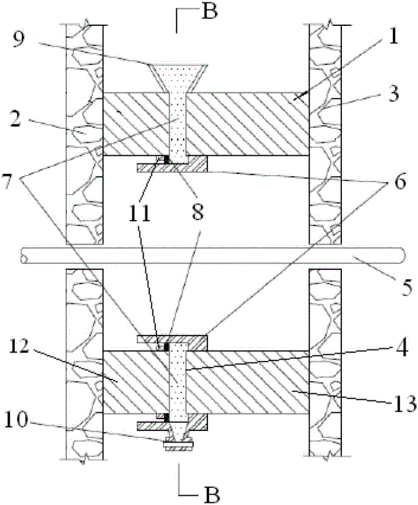
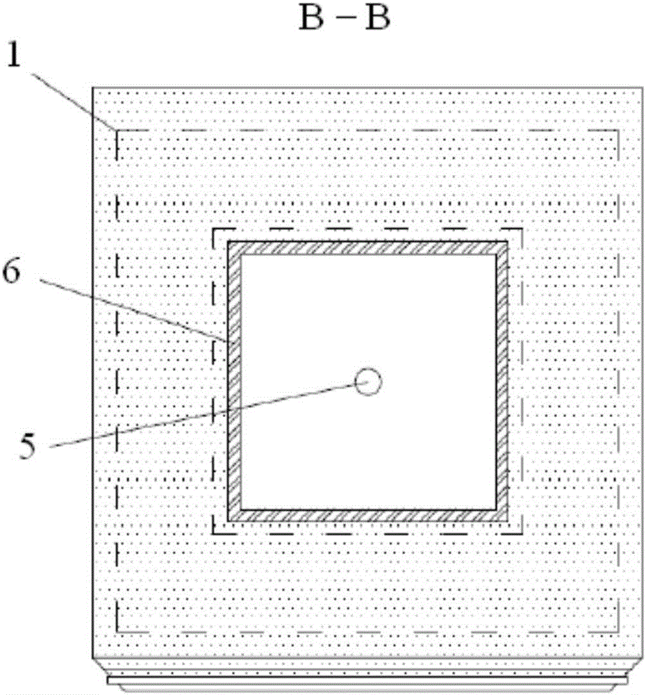
[0026] Such as figure 1 , 2 Shown is the shielding device for the spent fuel transfer channel provided by the present invention, the shielding device includes a shielding body 1, the shielding body 1 is a zigzag structure, and it is arranged in the fuel transfer channel between two adjacent buildings 2, 3 5 on. Expansion joints 4 are provided on the shielding body 1 to accommodate the relative displacement of the shielding bodies on both sides, thereby accommodating the relative movement between adjacent workshops. The expansion joint 4 is a straight gap, and the construction is relatively simple. The gaps are filled with lead borax to prevent beam leakage. The inner and outer sides of the expansion joint 4 are sealed with steel baffles to form a cavity with the shielding body of the fuel transfer channel at both end...


PUM


Abstract

The invention relates to a spent fuel transfer channel shielding device which is arranged on a fuel transport channel (5) between two adjacent plants. The shielding device comprises a shielding body (1) which is a square-shaped structure. The shielding body (1) is provided with an expansion joint (4) whose inner and outer side are blocked by baffle plates, thus a cavity is formed between the expansion joint and the shielding body. The shielding body is filled with a granular shielding material. By using the shielding device of the invention, the relative movement between the adjacent plants can be satisfied, the damage of the shielding body on the fuel transport channel is avoided, the radiation shielding requirement of a spent fuel component with a short transfer cooling time can be satisfied, the structure is simple, and the construction is convenient.

Description

technical field [0001] The invention belongs to the technical field of radiation shielding of nuclear island powerhouses of nuclear power plants, and in particular relates to a shielding device for a spent fuel transfer channel, which is mainly suitable for spent fuel with a relatively short cooling time requirement in nuclear power plants. Background technique [0002] The fuel transfer channel is the only way for new fuel and spent fuel to enter and exit the reactor building. Due to the strong radioactivity of the spent fuel, the shielding design of the fuel transfer channel has great influence on the design of the entire nuclear island plant, radiation zoning, personnel exposure dose evaluation and reactor safety. operation and maintenance have a significant impact. [0003] Under normal circumstances, the reactor core is unloaded after 7 to 14 days of shutdown cooling. After such a period of cooling, the spent fuel assembly is still very radioactive, and the requirements...

Claims


Application Information

Patent Timeline
IPC IPC(8): G21D1/02G21F3/00G21F1/02
CPCG21D1/02G21F1/02G21F3/00Y02E30/00
Inventor 张普忠米爱军王晓霞刘耸田英男杨德锋尤伟高桂玲邱林毛亚蔚
Owner CHINA NUCLEAR POWER ENG CO LTD
Learn More