Wireless electric energy transmission system and wireless electric energy transmission method

A technology of wireless energy transmission and electric energy, applied in the direction of electrical components, circuit devices, etc., can solve problems such as input fuse blown, switching power supply circuit damage, lower output voltage of the receiving end, etc., to suppress surge current and avoid surge The effect of current

Active Publication Date: 2017-03-22
QINGDAO LU YU ENERGY TECH CO LTD
View PDF7 Cites 8 Cited by
  • Summary
  • Abstract
  • Description
  • Claims
  • Application Information

AI Technical Summary

Problems solved by technology

Such a large surge current amplitude at the moment the power is turned on will often cause damage to the subsequent circuit of the switching power supply, blown the input fuse, and sometimes even burn out the contacts of the closing switch. not on the gate
[0005] (2) When the inverter circuit at the transmitting end is directly powered on, the LC series resonance (including the transmitting coil, capacitor and receiving coil) will also generate an instantaneous surge current, causing damage to the inverter circuit components
[0006] (3) When the load of the receiving end is switched (from light load to heavy load), it will also cause temporary detuning and lower the rectified output voltage of the receiving end, resulting in unstable operation of the receiving end system
[0007] The above-mentioned reasons will cause the switching power supply to be unable to use normally, and in the current prior art, there is no better solution for the above-mentioned problems

Method used


Image

  • Wireless electric energy transmission system and wireless electric energy transmission method
  • Wireless electric energy transmission system and wireless electric energy transmission method
  • Wireless electric energy transmission system and wireless electric energy transmission method

Examples


Embodiment Construction

[0032] In the following, the present invention will be specifically described through exemplary embodiments. It should be understood, however, that elements, structures and characteristics of one embodiment may be beneficially incorporated in other embodiments without further recitation.

[0033] In the description of the present invention, it should be noted that the terms "first" and "second" are used for description purposes only, and should not be understood as indicating or implying relative importance.

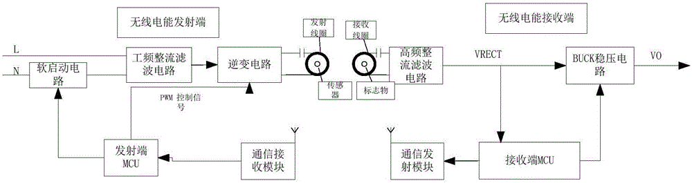
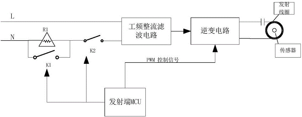
[0034] see figure 1 , is a block diagram of the wireless power transmission system of the present invention. Such as figure 1 As shown, the wireless power transmission system of the present invention includes a wireless transmitter connected to the power grid, and a wireless receiver capable of receiving power from the wireless transmitter. The communication receiving module; the external load of the wireless receiving end, including the receiving coil that can receiv...


PUM


Abstract

The invention provides a wireless electric energy transmission system and a wireless electric energy transmission method. Through setting a multi-stage start circuit, a surge current of a transmitting terminal power frequency rectification filter circuit in a powered-on state is inhibited; through step-by-step opening of a duty ratio carried out by a transmitting terminal MCU, a surge current of an LC resonance circuit on an inversion loop is inhibited; through controlling an opening time sequence of a back-stage BUCK voltage stabilizing circuit, influence of load switching on system start is inhibited. The method is advantaged in that problems of the surface currents of the transmitting terminal power frequency rectification filter circuit and the LC resonance inversion circuit in the powered-on state and system stability and reliability of load switching in a start process can be effectively solved.

Description

technical field [0001] The invention belongs to the field of wireless power transmission, and in particular relates to the field of wireless power transmission that can be activated in stages. Background technique [0002] The wireless power transmission system converts electric energy into other forms of relay energy (such as electromagnetic field energy, laser, microwave and mechanical wave, etc.) Realize wireless power transmission. [0003] The wireless power transmission system is usually composed of four parts: the power frequency rectification and filter circuit at the transmitting end, the inverter circuit at the transmitting end, the high frequency rectification and filtering circuit at the receiving end, and the voltage stabilizing circuit at the receiving end. Each part will generate an instantaneous surge current when it is powered on . The following is a specific analysis of the surge current for each part: [0004] (1) The power frequency rectification filte...

Claims


Application Information

Patent Timeline
Patent Type & Authority Applications(China)
IPC IPC(8): H02J50/12
CPCY02T10/70
Inventor 李聃孙佳昕
Owner QINGDAO LU YU ENERGY TECH CO LTD
Why Eureka
Try Eureka