A reluctance magnetic face gear set for orthogonal shaft transmission
A reluctance type, orthogonal axis technology, applied in the direction of electric components, electric brakes/clutches, permanent magnet clutches/brakes, etc., can solve complex structures, high costs of permanent magnet plane gears and bevel gears, and difficulties in manufacturing and assembling and other issues, to achieve the effect of high transmission efficiency, good quick response ability and cost reduction
- Summary
- Abstract
- Description
- Claims
- Application Information
AI Technical Summary
Problems solved by technology
Method used
Image
Examples
specific Embodiment approach 1
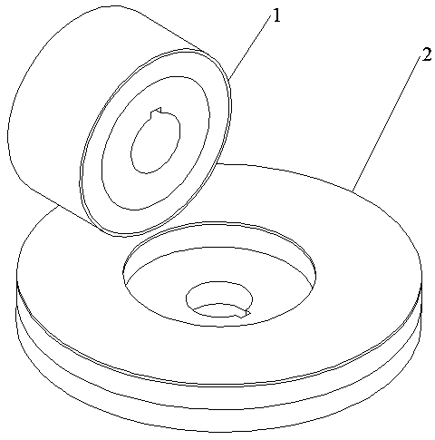
[0040] Specific implementation mode one: as figure 1 , Figure 20 and Figure 21 As shown, a reluctance magnetic surface gear set for orthogonal shaft transmission in this embodiment comprises two wheels, the two wheels are a cylindrical wheel 1 and a flat wheel 2, and the The flat wheel 2 is arranged horizontally, the cylindrical wheel 1 is arranged above the flat wheel 2, and the centerlines of the cylindrical wheel 1 and the flat wheel 2 are perpendicular to each other, and there is an air gap between the cylindrical wheel 1 and the flat wheel 2 (theoretical In general, the smaller the air gap, the greater the torque that can be transmitted, but it should be determined comprehensively in combination with the actual installation space and the torque required to be transmitted); when one of the wheels is a driving wheel, the other wheel is a driven wheel, so The driving wheel described above drives the driven wheel to rotate through magnetic resistance; when one of the whee...
specific Embodiment approach 2
[0041] Specific implementation mode two: as figure 1 , figure 2 , image 3 , Figure 9 , Figure 20 and Figure 21 As shown, the reluctance magnetic surface gear set for orthogonal shaft transmission described in the first embodiment, when the column wheel 1 is a permanent magnet column wheel (concentrated magnetic flux, surface-mounted , Halbach array type, built-in any one of the four structures), the plane wheel 2 is a mechanical plane wheel;
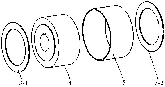
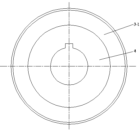
[0042]The permanent magnet type cylindrical wheel includes a front end ring 3-1, a rear end ring 3-2, a cylindrical wheel main body 4 and an outer protective cover 5; the front end ring 3-1, the rear end ring 3-2 and the outer protective cover The sleeves 5 are all made of non-magnetic materials (such as stainless steel or glass ribbon), and the front end ring 3-1 and the rear end ring 3-2 are all fixed on the front end face and the rear end face of the cylindrical wheel main body 4 by means of bonding. The outer protective co...
specific Embodiment approach 3
[0046] Specific implementation mode three: as Figure 4 As shown in the second embodiment, a reluctance magnetic surface gear set for orthogonal shaft transmission, the cylindrical wheel main body 4 adopts a magnetic flux concentration structure, and the cylindrical wheel main body 4 includes a cylindrical wheel yoke 9. A plurality of tile-shaped permanent magnets 6 and a plurality of tile-shaped iron cores 7; the plurality of tile-shaped permanent magnets 6 includes a plurality of first-type tile-shaped permanent magnets 6-1 and a plurality of second-type permanent magnets A tile-shaped permanent magnet 6-2; the cylindrical wheel yoke 9 is provided with an axial central hole 9-1, and the inner wall of the axial central hole 9-1 of the cylindrical wheel yoke 9 is provided with a useful Keyway 1 9-2 matched with shafting 1;
[0047] The plurality of first-type tile-shaped permanent magnets 6-1, the plurality of tile-shaped iron cores 7 and the plurality of second-type tile-sha...
PUM
 Abstract
Description
Claims
Application Information
 - R&D
- Intellectual Property
- Life Sciences
- Materials
- Tech Scout
- Unparalleled Data Quality
- Higher Quality Content
- 60% Fewer Hallucinations
Browse by: Latest US Patents, China's latest patents, Technical Efficacy Thesaurus, Application Domain, Technology Topic, Popular Technical Reports.
© 2025 PatSnap. All rights reserved.Legal|Privacy policy|Modern Slavery Act Transparency Statement|Sitemap|About US| Contact US: help@patsnap.com


