Sound system with code display and verification

A technology for verifying functions and sound systems, applied in transducer circuits, signal processing, sensor components, etc., can solve the problems of delaying time, unable to detect microphones, affecting the normal progress of sound reinforcement, etc., to achieve the effect of improving reliability

Active Publication Date: 2019-05-07
WEIFANG UNIVERSITY
View PDF7 Cites 0 Cited by
  • Summary
  • Abstract
  • Description
  • Claims
  • Application Information

AI Technical Summary

Problems solved by technology

[0003] The audio system mainly includes microphones, mixers, power amplifiers and speakers, etc. There is often a problem with the audio system currently in use: the person using the microphone starts to speak, but finds that the microphone cannot produce sound, which affects the quality of the performance, delays time, and appears This kind of situation is what the tuner is most worried about, but this kind of performance accident is hard to avoid, no matter how much preparation is done in advance, this kind of situation will still happen
Although the tuner can do sufficient debugging work before the start, it is difficult to avoid failures due to the large number of people in an event, time constraints, and many people are not familiar with the use of microphones.
[0005] When the tuner tests the microphone, he usually inputs a sound signal at the microphone end, and then listens to see if there is any sound output from the speaker, but it is impossible to do this test after the program starts, and the tuner cannot detect whether the microphone is connected to the mixer. Therefore, if there is a problem with the microphone after the program starts, and it cannot be found in time, there will be a situation where the microphone does not make sound, which will affect the normal progress of the sound reinforcement, waste time, affect the effect, and sometimes cause irreparable Loss

Method used


Image

  • Sound system with code display and verification
  • Sound system with code display and verification
  • Sound system with code display and verification

Examples


Embodiment Construction

[0024] In order to make the object, technical solution and advantages of the present invention clearer, the present invention will be further described in detail below in conjunction with the accompanying drawings and embodiments. It should be understood that the specific embodiments described here are only used to explain the present invention, not to limit the present invention.

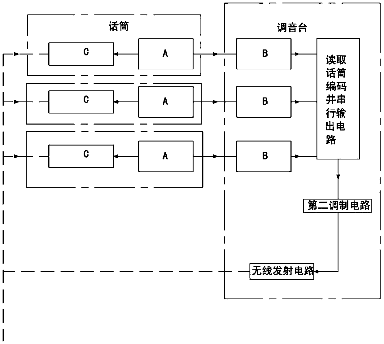
[0025] Such as figure 1 , figure 2 , image 3 and Figure 4 As shown in the figure, an audio system with code display and verification functions includes a microphone and a mixer, the output end of the microphone is connected to the microphone input interface on the mixer, and an acoustic-electric conversion circuit is provided in the microphone.

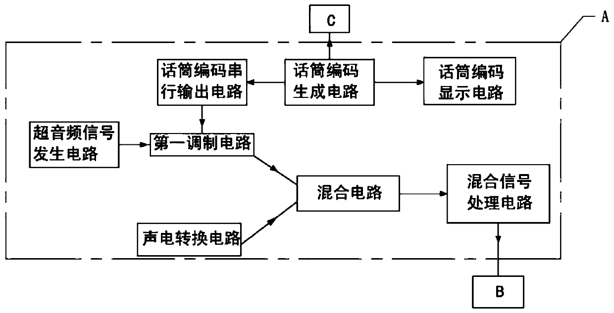
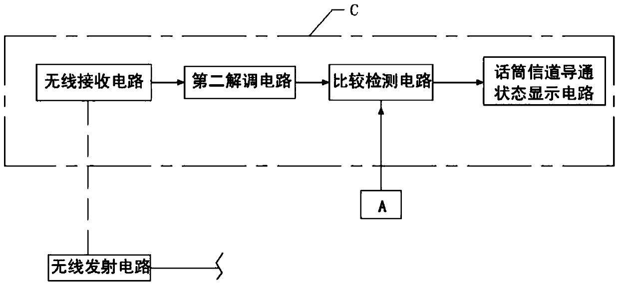
[0026] Such as figure 2 As shown, the microphone of the present invention is also provided with a super-audio signal generation circuit, a microphone code generation circuit, a microphone code serial output circuit, a microphone code display circui...


PUM


Abstract

The invention discloses an audio system with code display and verification functions. The audio system comprises a microphone and a sound console. A superaudio signal generating circuit, a microphone code generating circuit, a microphone code serial output circuit, a microphone code display circuit, a first modulation circuit, a mixing circuit, a mixed signal processing circuit, an acoustic-electric conversion circuit, a comparison and detection circuit, a second demodulation circuit, a wireless receiving circuit and a microphone channel conduction state display circuit are arranged in the microphone; and the sound console is provided with a microphone input interface, a signal allocation circuit, a filter amplifier circuit, a first demodulation circuit, a microphone code reading and display circuit, an audio signal processing circuit, a microphone code reading and parallel series output circuit, a second modulation circuit and a wireless transmitting circuit. The system can continuously display the conduction state of the microphone channel in real time, so faults can be removed in time, and the situation that no conduction is found after use is avoided.

Description

technical field [0001] The invention relates to the technical field of audio equipment, in particular to an audio system with code display and verification functions. Background technique [0002] Audio system equipment is the most widely used media equipment, especially in education, business, entertainment, exhibition and other industries. [0003] The audio system mainly includes microphones, mixers, power amplifiers and speakers, etc. There is often a problem with the audio system currently in use: the person using the microphone starts to speak, but finds that the microphone cannot produce sound, which affects the quality of the performance, delays time, and appears This situation is what the tuner is most worried about, but this kind of performance accident is hard to avoid, no matter how much preparation is done in advance, this kind of situation will still happen. [0004] The common reasons for the microphone not making sound are: the person using the microphone tu...

Claims


Application Information

Patent Timeline
Patent Type & Authority Patents(China)
IPC IPC(8): H04R3/00
CPCH04R3/00H04R2430/00
Inventor 杨洁戴长志
Owner WEIFANG UNIVERSITY
Why Eureka
Try Eureka