Radiant heater

A radiant heater and radiant heat technology, applied in electric heating devices, air heaters, fluid heaters, etc., can solve the problems of increasing heat capacity of radiant heater devices

Inactive Publication Date: 2017-03-22
DENSO CORP
View PDF10 Cites 5 Cited by
  • Summary
  • Abstract
  • Description
  • Claims
  • Application Information

AI Technical Summary

Problems solved by technology

However, in the structure described in Patent Document 3 or Patent Document 4, a heat sink for radiating radiant heat is required
There is a problem that the heat dissipation part increases the heat capacity of the radiation heater device
In addition, problems in the production process and problems in the price may arise in the heat dissipation part

Method used


Image

  • Radiant heater
  • Radiant heater
  • Radiant heater

Examples


no. 1 approach

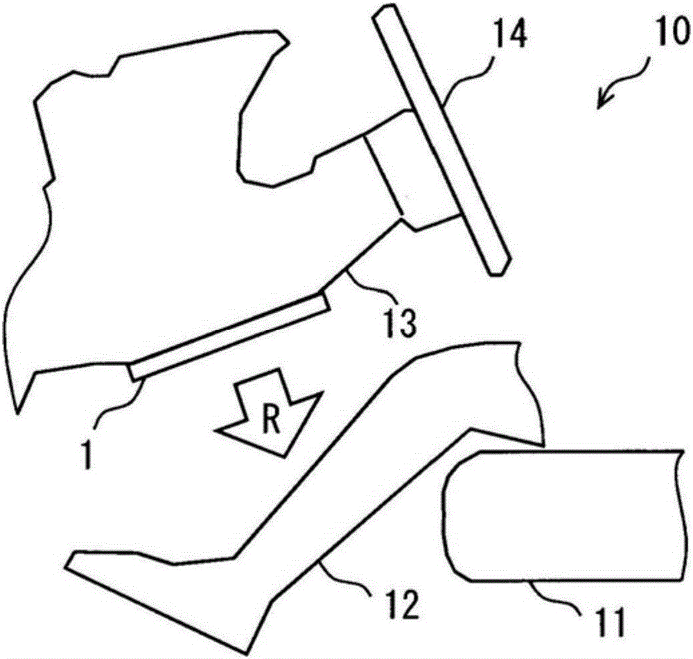
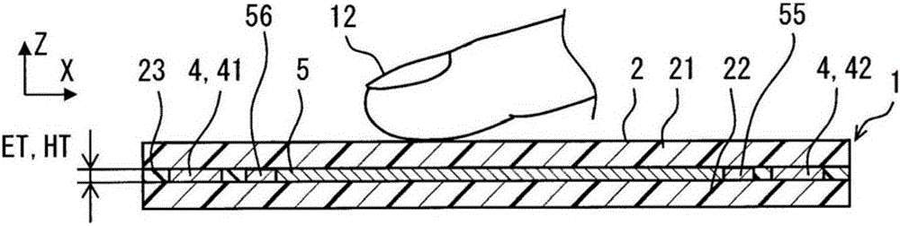
[0044] exist figure 1 Among them, the radiant heater device 1 of the first embodiment is installed in a room of a moving body such as a road vehicle, a ship, and an aircraft. The device 1 forms part of a heating device 10 for indoor use. The device 1 is an electric heater that is supplied with power from a power source such as a battery and a generator mounted on a mobile body to generate heat. The device 1 is formed in a thin plate shape. The device 1 generates heat when power is supplied. In order to warm an object positioned in a direction perpendicular to the surface of the device 1 , the device 1 radiates radiant heat R mainly in a direction perpendicular to its surface.

[0045] A seat 11 for seating an occupant 12 is provided indoors. The device 1 is installed indoors so as to radiate radiant heat R to the feet of the occupant 12 . The device 1 can be used as a device for quickly providing warmth to the occupant 12 immediately after the heating device 10 is activat...

no. 2 approach

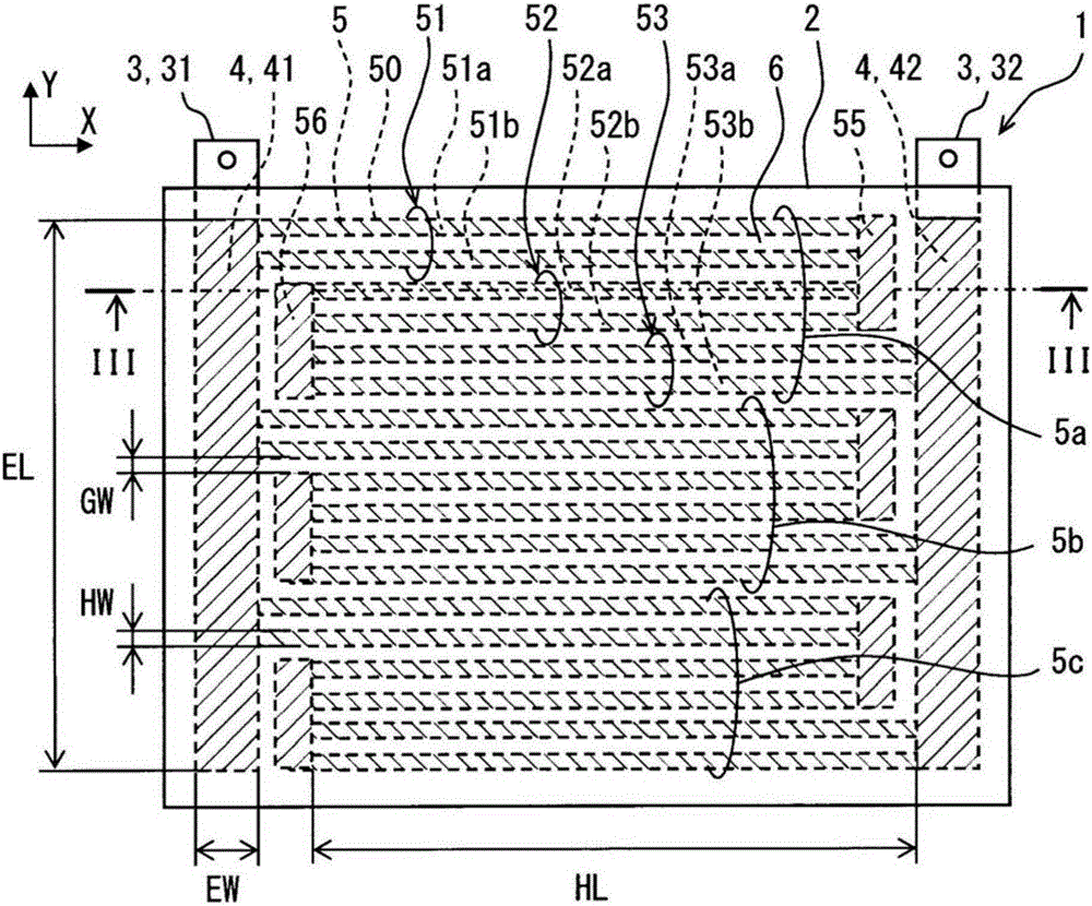
[0122] This embodiment is a modified example based on the previous embodiment. In the above-described embodiment, the pair of electrodes 41 and 42 are arranged along the opposite sides of the substrate portion 2 , and the plurality of heating belts 5 a , 5 b and 5 c are arranged between the electrodes 41 and 42 . Instead, the plurality of electrodes 41 , 42 , 55 , and 56 and the plurality of heating wires 50 can be arranged in various ways.

[0123] exist Figure 9 In the illustrated embodiment, the pair of electrodes 41 and 42 are arranged in a concentrated manner only along one side of the substrate portion 2 . The heat generating portion 205 is provided by connecting a plurality of heat generating wires 50 in series between the pair of electrodes 41 and 42 . The heat generating unit 205 has a plurality of parallel groups 51 , 52 , 53 , and 54 . These parallel groups 51 , 52 , 53 , and 54 are each configured by connecting a plurality of heating wires 50 in parallel. In o...

no. 3 approach

[0125] This embodiment is a modified example based on the previous embodiment. In the above-described embodiment, a portion for connecting a plurality of heating wires 50 in parallel is provided in one heating belt. Instead, the parallel connection portion of the plurality of heating wires 50 may not be provided in one heating belt, but only the series connection of the plurality of heating wires 50 may be used to constitute one heating belt.

[0126] exist Figure 10 In the illustrated embodiment, the heat generating portion 305 has a plurality of heat generating belts. In the figure, six heating zones are illustrated. One heating belt is provided by connecting a plurality of heating wires 50 in series. The plurality of heating wires 51a, 52a, and 53a are connected in series through electrodes 355 and 356 . These electrodes 355 and 356 do not connect the plurality of heating wires 50 in parallel, but only in series. In this embodiment, electrodes 355, 356 also provide st...


PUM


Abstract

A heat-generating section of this radiant heater has a plurality of heat-generating wires. The plurality of heat-generating wires are connected in parallel such that a plurality of parallel groups of the wires are formed by electrodes. Further, the plurality of parallel groups are connected in series by the electrodes. The heat-generating section is set such that a radiant temperature, at which radiant heat that would make a person feel warm can be radiated, can be reached. The thermal resistance of the heat-generating section is set such that when an object contacts the surface of the section, the temperature of the site of contact with the object is decreased to a suppressed temperature lower than the radiant temperature. The temperature of the heat-generating section increases rapidly in response to electric conduction. When there is contact with an object, the temperature of the heat-generating section decreases rapidly.

Description

[0001] Cross-reference to related applications [0002] The present application is based on Japanese Patent Application No. 2014-149054 filed on July 22, 2014, and the disclosure of the basic application is incorporated herein by reference. technical field [0003] The present invention relates to a radiant heater device for heating an object by radiation. Background technique [0004] Patent Document 1 to Patent Document 4 disclose radiant heater devices. The device is disposed in the interior of the vehicle opposite the occupant. [0005] prior art literature [0006] Patent Literature [0007] Patent Document 1: Japanese Patent Laid-Open No. 2012-56531 [0008] Patent Document 2: Japanese Patent Laid-Open No. 2012-228896 [0009] Patent Document 3: Japanese Patent Laid-Open No. 2014-944 [0010] Patent Document 4: Japanese Patent Laid-Open No. 2014-3000 [0011] The above-described device is effective as a device for assisting the vehicle heating device to give a w...

Claims


Application Information

Patent Timeline
Patent Type & Authority Applications(China)
IPC IPC(8): B60H1/22B60H1/03H05B3/20
CPCB60H1/2215H05B2203/032B60H1/2226F24H3/002H05B3/24B60H1/2225
Inventor 佐合康弘加古英章石川公威生出裕康关秀树近藤宏司多田和夫井之口正晃
Owner DENSO CORP
Why Eureka
Try Eureka