Combustion chamber structure for sparkignition engine

a combustion chamber and sparkignition engine technology, applied in the direction of combustion engines, engine ignition, machines/engines, etc., can solve the problem that the structure cannot always ensure practically valuable combustion, and achieve the effect of preventing the pre-ignition of unburnt fuel, reducing the pressure and temperature of the inlet cylinder, and reducing the risk of engine failur

Active Publication Date: 2007-03-15
MAZDA MOTOR CORP
View PDF1 Cites 22 Cited by
  • Summary
  • Abstract
  • Description
  • Claims
  • Application Information

AI Technical Summary

Benefits of technology

[0015] Through various researches with a focus on a combustion mode designed to perform combustion at a low speed in an initial primary combustion period (an initial stage of a primary combustion period where a combustible mass is burnt from 10% to less than 90%, wherein the combustible mass is burnt from 10% up to less than 50% in the initial stage), so as to suppress an increase in in-cylinder pressure and temperature and effectively prevent preignition of unburnt fuel to obtain a higher anti-Knocking performance, and then burn unburnt fuel at a high speed in a final primary combustion period (a final stage of the primary combustion period, wherein the combustible mass is burnt from 50% up to less than 90% in the last stage) and rapidly complete the combustion so as to prevent self-ignition due to residual unburnt fuel to obtain a higher anti-Knocking performance, whereby Knocking can be effectively suppressed mostly without extending the primary combustion period for the entire combustion (in this specification, this combustion mode will hereinafter be refereed to as “final-stage centered combustion”), the inventors has found the following combustion chamber structure for a spark-ignition engine, capable of readily performing the final-stage centered combustion.

Problems solved by technology

In reality, even if a higher compression ratio is achieved, for example, by ingeniously designing a combustion chamber structure as described above, such a structure cannot always ensure practically valuable combustion.

Method used


Image

  • Combustion chamber structure for sparkignition engine
  • Combustion chamber structure for sparkignition engine
  • Combustion chamber structure for sparkignition engine

Examples


first embodiment

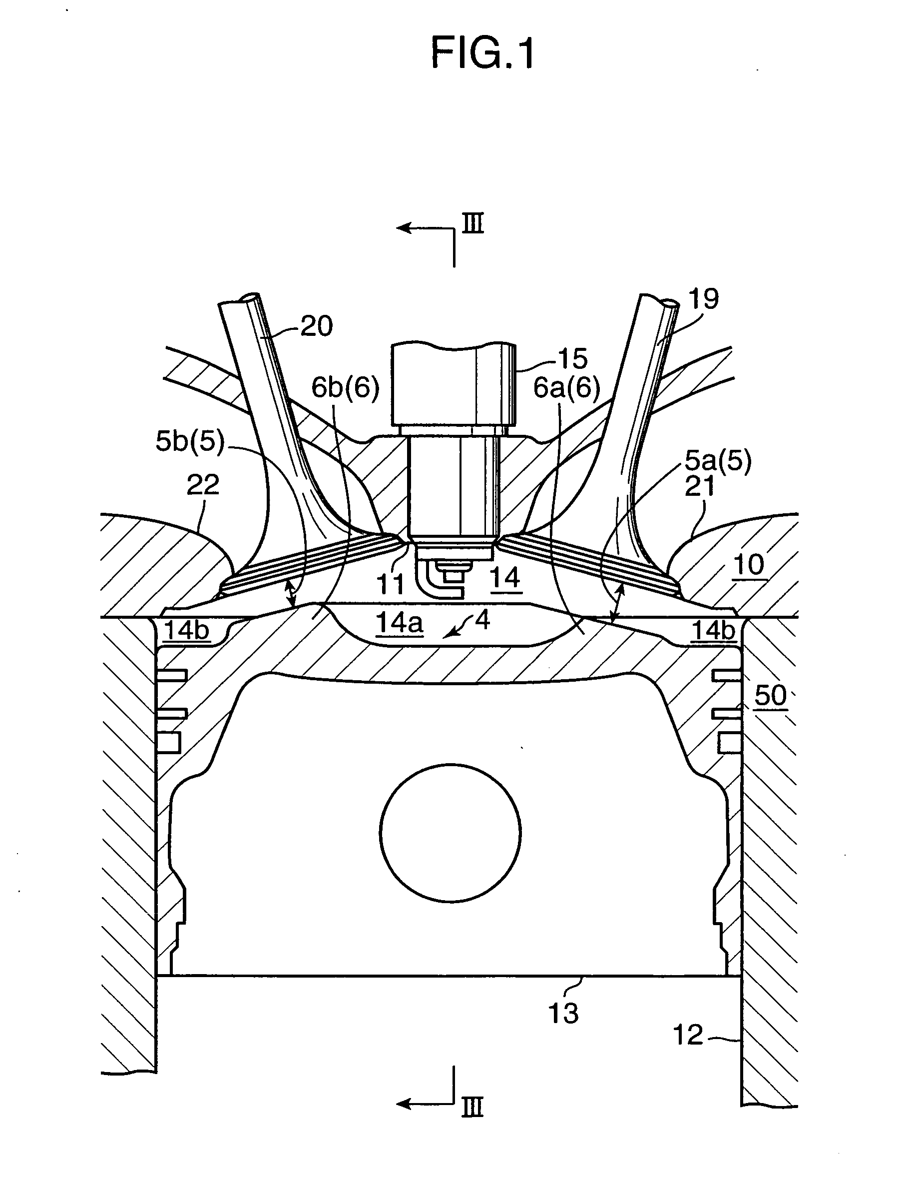
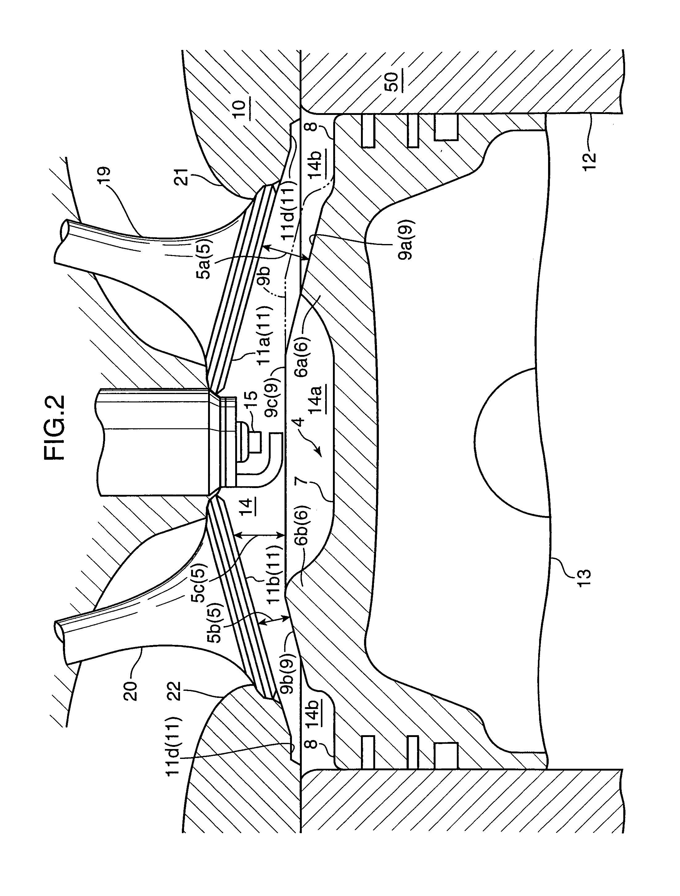
[0036]FIG. 1 is a vertical sectional view showing a combustion chamber structure for a spark-ignition engine according to the present invention. FIG. 2 is a fragmentary enlarged view of the combustion chamber structure in FIG. 1. FIG. 3 is a sectional view taken along the line III-III in FIG. 1.

[0037] A combustion chamber 14 in the first embodiment is designed as a pent-roof type. In FIGS. 1 to 3, the combustion chamber 14 is shown under the condition that a piston 13 is at TDC (Top Dead Center). The combustion chamber 14 is a space surrounded by a cylinder bore (cylinder bore surface or wall) 12 of a cylinder block 50, a top surface 4 of the piston 13, and a ceiling wall 11 which is a bottom surface of a cylinder head 10 exposed to the combustion chamber 14). The ceiling wall 11 has an intake-side ceiling wall region 1la and an exhaust-side ceiling wall region 11b each formed in a roof shape.

[0038] A spark plug 15 is installed in the cylinder head 10 approximately at or around the...

second embodiment

[0079] With reference to FIG. 7 and FIGS. 8A to 8C, the present invention will be described below.

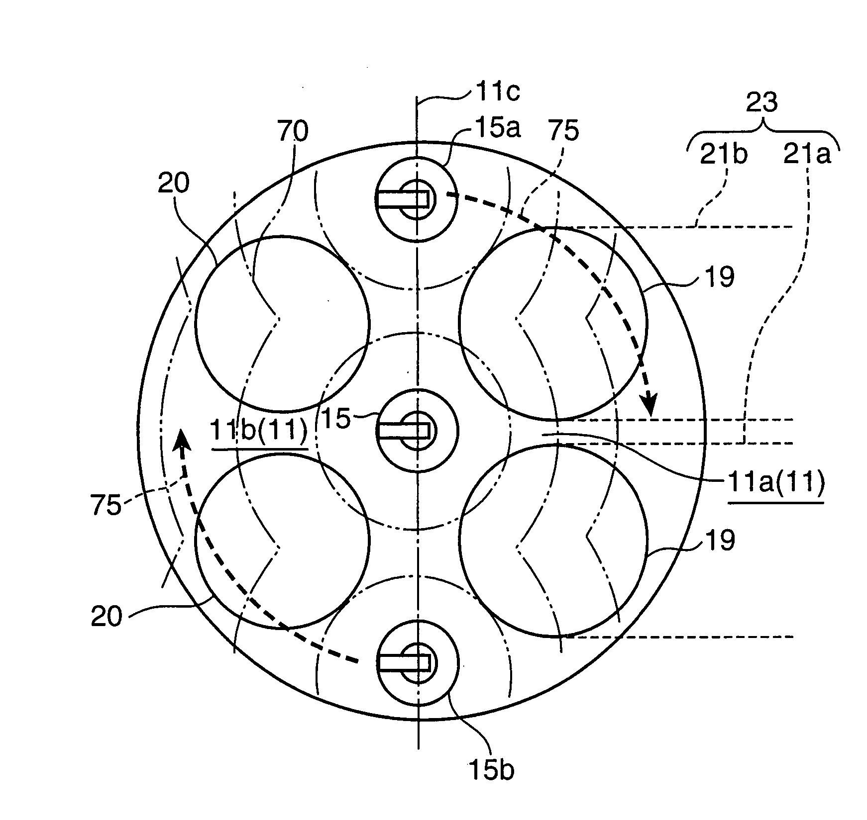
[0080]FIG. 7 is a sectional view showing a combustion chamber structure according to the second embodiment, taken along a line equivalent to the line III-III in FIG. 1. FIGS. 8A to 8C are explanatory diagrams of a swirl flow and a flame propagation, wherein FIG. 8A is a top plan view showing an intake-side ceiling wall, viewing from the side of a piston, and FIGS. 8B and 8C are schematic diagrams showing the configuration of a (secondary) intake port for a swirl generation intake system.

[0081] A major difference between the first and second embodiments is in that the combustion chamber structure according to the second embodiment is provided with a second spark plug 15a and a third spark plug 15b in addition to the spark plug 15 (see FIG. 7 and 8A), and a swirl generation intake system 23 (see FIG. 8A).

[0082] As shown in FIG. 7, the second spark plug 15a and the third spark plug 15b a...

third embodiment

[0111] While the normal tumble-type intake port for generating a stronger tumble flow in the exhaust-side zone is employed in the third embodiment, a reverse tumble-type intake port for generating a stronger tumble flow in the zone on the side of the cylinder bore wall may be employed. In this case, a height of the intake-side second convex area 6a may be increased (so that the height of the second convex area 6a becomes higher than that of the intake-side first convex area 6b) to allow the reverse tumble flow to collide with the second convex area 6a.

[0112] As described above based on the specific embodiments, according to one aspect of the present invention, there is provided a combustion chamber structure for a spark-ignition engine, which comprises a combustion chamber defined between a bottom surface of a cylinder head and a top surface of a piston in such a manner that the bottom surface of the cylinder head serves as a ceiling wall thereof, and a spark plug having a sparking...


PUM


Abstract

This invention relates to a combustion chamber structure for a spark-ignition engine, which comprises a combustion chamber defined between a bottom surface of a cylinder head and a top surface of a piston in such a manner that the bottom surface of the cylinder head serves as a ceiling wall thereof, and a spark plug having a sparking end protruding from the ceiling wall into the combustion chamber. In this combustion chamber structure, when the piston is at a top dead center, a principal space of the combustion chamber is comprised of a first combustion space around the sparking end of the spark plug and a second combustion space around a circumference of a cylinder bore. Further, the first combustion space and the second combustion space are communicated with each other through a small interspace zone where an interspace between the ceiling wall and the top surface of the piston is narrowed. The combustion chamber structure makes it possible to increase compression ratio in a practically effective manner.

Description

BACKGROUND OF THE INVENTION [0001] 1. Field of the Invention [0002] The present invention relates to a combustion chamber structure for a spark-ignition engine, and more specifically to a structure for a combustion chamber defined between a bottom surface of a cylinder head and a top surface of a piston in such a manner that the bottom surface of the cylinder head serves as a ceiling wall thereof. [0003] 2. Background Art [0004] In recent years, there has been an ever-growing need for improving engine fuel economy from not only economic aspects but also environmental aspects of measures for preventing global warming. In spark-ignition engines, the improvement in combustion efficiency is an effective approach for obtaining enhanced fuel economy, and an increase in compression ratio is one of dominant techniques therefor. [0005] A higher compression ratio can be achieved by reducing a combustion chamber volume relative to a cylinder volume. As a combustion chamber structure suitable f...

Claims


Application Information

Patent Timeline
Patent Type & Authority Applications(United States)
IPC IPC(8): F02B31/00F02P15/02F02B23/00
CPCF02B23/08F02B23/101F02B31/085Y02T10/146F02B2031/006Y02T10/125F02B2023/085Y02T10/12
Inventor YOHSO, TAKASHIYAMAKAWA, MASAHISASHISHIME, KOUJINISHIMOTO, TOSHIAKI
Owner MAZDA MOTOR CORP
Why Eureka
Try Eureka