Power conversion apparatus

a power conversion apparatus and power conversion technology, which is applied in the direction of electrical apparatus contruction details, battery/cell propulsion, transportation and packaging, etc., can solve the problems of increasing the power consumption difficult to suppress the temperature increase of semiconductor elements located in the relevant region, and insufficient cooling capability of the cooling mechanism, so as to save the power of the cooling mechanism and improve the fuel cost of the vehicle incorporating the power conversion apparatus. , the effect of reducing the cost of the fuel consumption

Inactive Publication Date: 2010-07-01
TOYOTA JIDOSHA KK
View PDF4 Cites 21 Cited by
  • Summary
  • Abstract
  • Description
  • Claims
  • Application Information

AI Technical Summary

Benefits of technology

[0028]Since the cooling capability of a cooling mechanism does not have to be increased in the power conversion apparatus set forth above, the power of the cooling mechanism can be saved. As a result, the fuel cost of the vehicle incorporating the power conversion apparatus can be improved. Moreover, downsizing of the power conversion apparatus can be realized since increase in the size of the cooling mechanism can be suppressed.
[0029]In a power conversion apparatus including a plurality of power converters of the present invention, temperature increase of semiconductor elements constituting each power converter can be suppressed. As a result, the area occupied by the element substrate can be reduced while ensuring the cooling performance for the semiconductor elements. Thus, downsizing of the power conversion apparatus can be realized.

Problems solved by technology

As a result, the cooling capability of the cooling mechanism will become insufficient at the region of high temperature.
There was a problem that it is difficult to suppress temperature increase of semiconductor elements located in the relevant region.
However, this method will needlessly increase power consumption of the cooling mechanism, causing degradation in the fuel cost for vehicles incorporating an IPM.
Moreover, in the case where a large-scale cooling mechanism having a higher cooling capability is provided, the size and cost of the IPM will be increased, which will conflict with the demand for downsizing imposed on an IPM due to space constraints during mounting.

Method used


Image

  • Power conversion apparatus
  • Power conversion apparatus
  • Power conversion apparatus

Examples


first embodiment

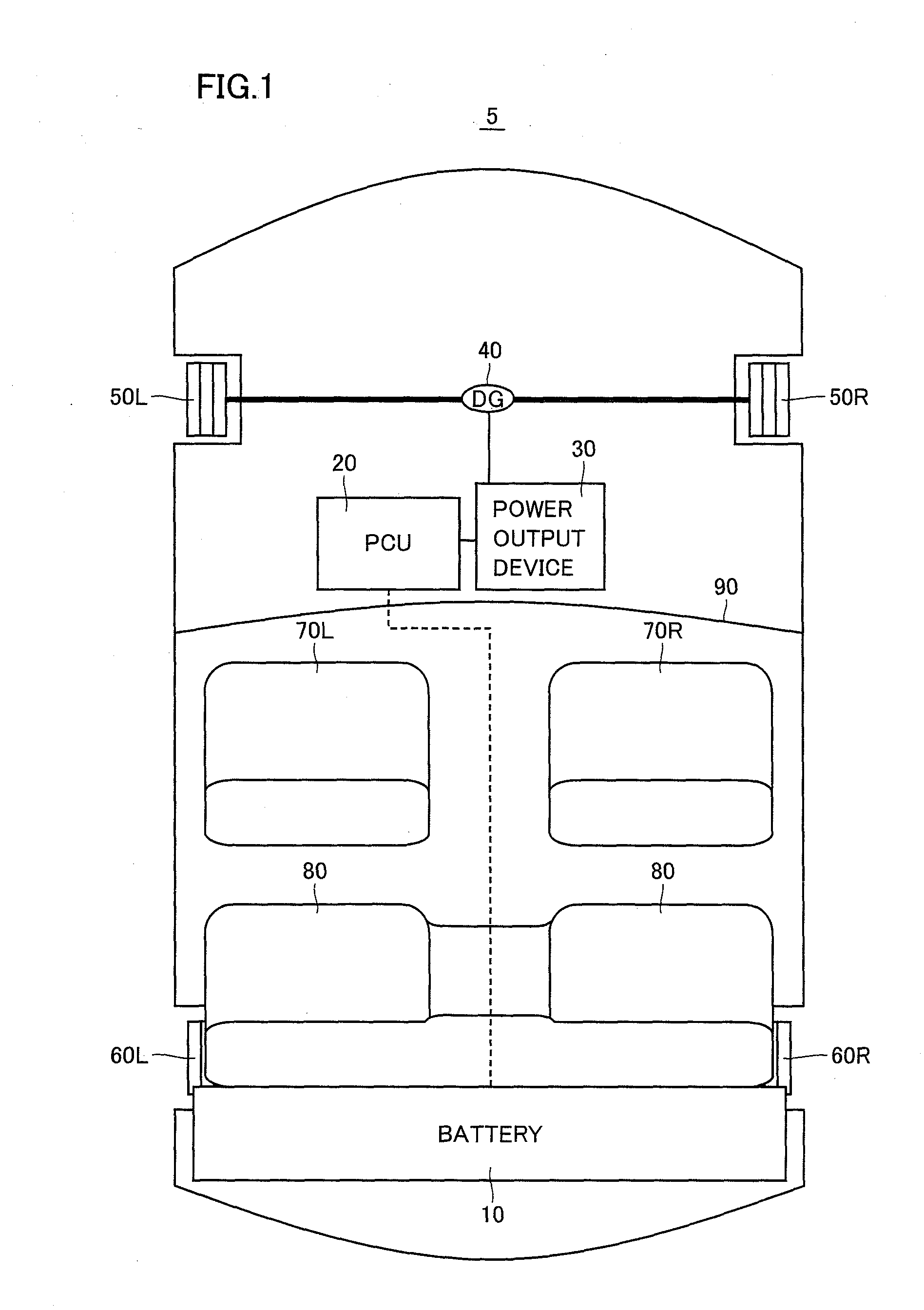
[0038]FIG. 1 is a schematic block diagram representing an entire configuration of a hybrid vehicle provided as an example of incorporating a power conversion apparatus of the present invention

[0039]Referring to FIG. 1a hybrid vehicle 5 includes a battery 10, a PCU (Power Control Unit) 20, a power output device 30, a differential gear (DG) 40, front wheels 50L, 50R, rear wheels 60L, 60R, front seats 70L, 70R, and a rear seat 80.

[0040]Battery 10 is arranged at the rearward side of rear seat 80. Battery 10 is electrically connected to PCU 20. PCU 20 is arranged utilizing the lower region of front seats 70L and 70R, i.e. the region under the floor. Power output device 30 is arranged at an engine room located forward of a dashboard 90. PCU 20 is electrically connected to power output device 30. Power output device 30 is coupled to DG 40.

[0041]Battery 10 that is a DC power supply is constituted of, for example, a secondary battery such as of nickel hydrogen or lithium ions. Battery 10 sup...

second embodiment

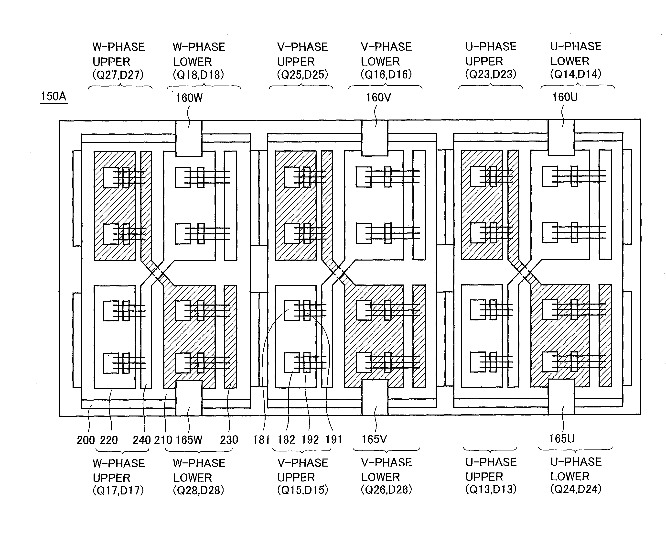
[0098]FIG. 7 represents a layout of an inverter module 150D that is a typical example of a semiconductor module according to a second embodiment of the present invention. For the sake of simplification in FIG. 7, only the U-phase arm of inverter module 150 shown in FIG. 3 is extracted and depicted. The illustration and description of the V-phase arm and W-phase arm having a similar configuration will not be repeated.

[0099]Referring to FIG. 7, in inverter module 150D, two semiconductor elements (IGBT element and diode element) constituting the same arm of the same phase are arranged in a displaced manner on insulation substrate 210.

[0100]Specifically, power switch Q13 of the U-phase upper arm in inverter 151 is constituted of IGBT elements 181 and 182 connected in parallel. In the present configuration, adjacent IGBT element 181 and IGBT element 182 are arranged so as to be displaced in the horizontal direction in FIG. 7. In accordance with such an arrangement of the two IGBT element...


PUM


Abstract

An inverter module has a first inverter driving a first electric load and a second inverter driving a second electric load, mounted on a common insulation substrate. In the first inverter, the arms of the U, V and W phases are arranged on the insulation substrate such that arms adjacent in the horizontal direction in the drawing are located displaced from each other in the vertical direction in the drawing. In the second inverter, the arms of the U, V and W phases are arranged on the insulation substrate such that arms adjacent in the horizontal direction in the drawing are displaced from each other in the vertical direction in the drawing. Moreover, the arm of the first inverter and the arm of the second inverter are arranged to be adjacent along the horizontal direction in the drawing. By such an arrangement, the in-plane temperature distribution can be rendered uniform without having to increase the area occupied by the insulation substrate.

Description

TECHNICAL FIELD[0001]The present invention relates to power conversion apparatuses, and more particularly, a power conversion apparatus including a plurality of power converters.BACKGROUND ART[0002]Recently, attention is focused on hybrid vehicles and electric vehicles as vehicles taking into account environmental issues. A hybrid vehicle includes, in addition to a conventional engine, a motor as the motive power supply, driven by a DC power supply via an inverter. In addition to achieving the power supply by driving the engine, the DC voltage from the DC power supply is converted into AC voltage by the inverter, and the converted AC voltage is used to rotate the motor to achieve motive power. An electric vehicle includes, as the motive power supply, a motor driven by a DC power supply via an inverter.[0003]An intelligent power module (IPM) incorporated in such hybrid vehicles or electric vehicles converts the DC power supplied from a DC power supply into AC power to drive the motor...

Claims


Application Information

Patent Timeline
Patent Type & Authority Applications(United States)
IPC IPC(8): H02M7/00
CPCH02M7/003H02M2001/008Y02T10/7005H01L2224/48139B60L50/51H01L2224/48137H01L2224/49175H01L2224/49111H01L2924/00H01L2924/13055Y02T10/70H02M1/008
Inventor YOSHINAGA, FUMITAKA
Owner TOYOTA JIDOSHA KK
Why Eureka
Try Eureka