Honeycomb structure

a honeycomb and structure technology, applied in the field of honeycomb structure, can solve the problems of difficult unitary joining of the catalyst to the heater, damage to the power source circuit, etc., and achieve the effect of suppressing the bias of heat generation and suppressing the bias of temperature distribution at the time of applying a voltag

Active Publication Date: 2013-02-21
NGK INSULATORS LTD
View PDF1 Cites 19 Cited by
  • Summary
  • Abstract
  • Description
  • Claims
  • Application Information

AI Technical Summary

Benefits of technology

[0009]The present invention has been made in view of the aforementioned problems and aims to provide a honeycomb structure which functions not only as a catalyst carrier, but also as a heater by applying a voltage and which can suppress bias of a temperature distribution when the voltage is applied.
[0016]In a honeycomb structure of the present invention, since the honeycomb structure section has an electric resistivity of 1 to 200 Ωcm, even if an electric current is sent by the use of a power source having a high voltage, the current does not flow excessively, and it can suitably be used as a heater. In addition, since “each of the pair of electrode sections is formed into a band-like shape extending in a cell extension direction of the honeycomb structure section; in a cross section perpendicular to the cell extension direction, one of the pair of electrode sections is disposed across the center of the honeycomb structure section from the other electrode section of the pair of electrode sections; and, in a cross section perpendicular to the cell extension direction, 0.5 time the central angle of each of the electrode sections is 15 to 65°”; bias of a temperature distribution at the time of applying a voltage can be suppressed. In particular, in a cross section perpendicular to the cell extension direction, since 0.5 time the central angle of each of the electrode sections is 15 to 65°, bias of a current flowing through the honeycomb structure section can be suppressed when a voltage is applied between the pair of electrode sections, and thereby suppressing bias of heat generation in the honeycomb structure section.

Problems solved by technology

However, since a metal heater has a low electrical resistance, when a power source having such a high voltage was used, there was a problem of damaging the power source circuit because a current flows extremely.
In addition, when the heater was made of metal, it was difficult to unitarily join a catalyst to the heater because it was hard to load a catalyst even if the heater was processed to have a honeycomb structure.

Method used


Image

  • Honeycomb structure
  • Honeycomb structure
  • Honeycomb structure

Examples


example 1

[0119]A silicon carbide (SiC) powder and a metal silicon (Si) powder were mixed together at a mass ratio of 80:20; and hydroxypropylmethyl cellulose as the binder and a water-absorbent resin as the pore former were added to them, and water was added to obtain a forming raw material; and the forming raw material was kneaded by a vacuum kneader to produce a circular columnar kneaded material. The binder content was 7 parts by mass with respect to 100 parts by mass of the total of the silicon carbide (SiC) powder and the metal silicon (Si) powder, the pore former content was 3 parts by mass with respect to 100 parts by mass of the total of the silicon carbide (SiC) powder and the metal silicon (Si) powder, and the water content was 42 parts by mass with respect to 100 parts by mass of the total of the silicon carbide (SiC) powder and the metal silicon (Si) powder. The average particle diameter of the silicon carbide powder was 20 and the average particle diameter of the metal silicon p...

examples 2 to 13

Comparative Examples 1, 2

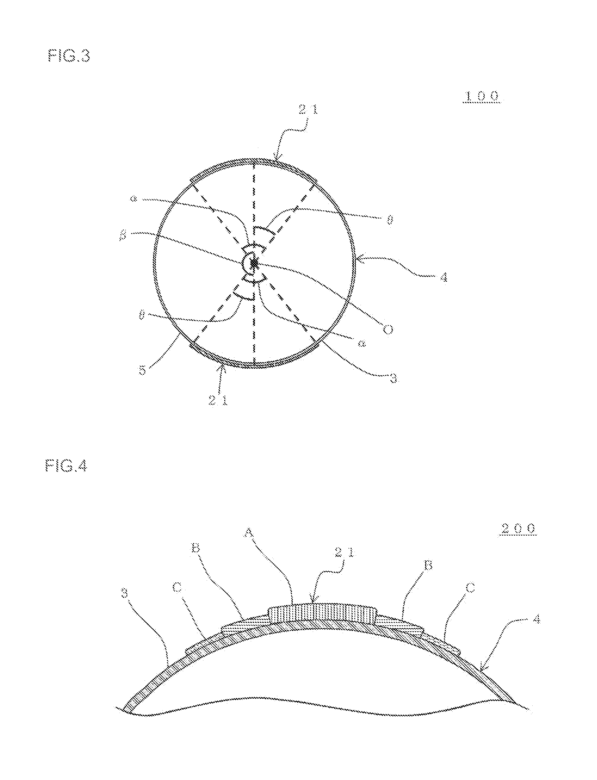
[0130]Each of the honeycomb structures was manufactured in the same manner as in Example 1 except that “0.5 time the central angle in a cross section perpendicular to the cell extension direction of each of the two electrode sections” and “thickness of the two electrode sections” were changed as shown in Table 1. The “maximum temperature” of the honeycomb structure was measured in the same manner as in Example 1. The results are shown in Table 1.

[0131]From Table 1, it is understood that the maximum temperature of the honeycomb structure is low when the “value of 0.5 time the central angle in a cross section perpendicular to the cell extension direction of each of the two electrode sections of the honeycomb structure” is 15 to 65°. The low maximum temperature of the honeycomb structure means that bias of the temperature distribution in the honeycomb structure is suppressed. Incidentally, the aforementioned maximum temperature of 200° C. or less of the honeyco...


PUM

PropertyMeasurementUnit
electric resistivityaaaaaaaaaa
central angleaaaaaaaaaa
electric resistivityaaaaaaaaaa

Abstract

A honeycomb structure is provided with a pair of electrode sections disposed on the side face of the honeycomb structure section. The honeycomb structure section has an electric resistivity of 1 to 200 Ωcm, and each of the pair of electrode sections is formed into a band-like shape extending in a cell extension direction of the honeycomb structure section. In a cross section perpendicular to the cell extension direction, one electrode section of the pair of electrode sections is disposed across the center O of the honeycomb structure section from the other electrode section of the pair of electrode sections. In a cross section perpendicular to the cell extension direction, 0.5 time the central angle of each of the electrode sections is 15 to 65°.

Description

TECHNICAL FIELD[0001]The present invention relates to a honeycomb structure and, more specifically, relates to a honeycomb structure which functions not only as a catalyst carrier, but also as a heater by applying a voltage and which can suppress bias of a temperature distribution when the voltage is applied.BACKGROUND ART[0002]Conventionally, a cordierite honeycomb structure having a catalyst loaded thereon has been used for treating harmful substances in exhaust gas discharged from an automobile engine. It is known that a honeycomb structure formed of a silicon carbide based sintered body is used for purifying exhaust gas (see, e.g., Patent Document 1).[0003]In the case of treating exhaust gas by a catalyst loaded on a honeycomb structure, it is necessary to raise temperature of the catalyst up to predetermined temperature. However, since catalyst temperature is low upon engine start-up, there was a problem of insufficient purification of exhaust gas.[0004]Therefore, there is stud...

Claims


Application Information

Patent Timeline
Patent Type & Authority Applications(United States)
IPC IPC(8): H05B3/10
CPCB01D53/32B01D53/94F01N3/2828F01N2240/16F01N2260/08B01D46/2425F01N2330/30F01N3/2026Y02T10/26B01J35/04F01N2330/06Y02T10/12
Inventor SAKASHITA, SATOSHIOMIYA, YOSHIMASA
Owner NGK INSULATORS LTD
Why Eureka
Try Eureka