Monitoring and measuring of multiple light sources especially heliostats

A technology for heliostats and measuring equipment, which is applied to solar collectors, optics, and optical components in specific environments, and can solve problems such as inaccurate heliostat calibration, the impact of heliostat downtime, and unresolved issues.

Active Publication Date: 2017-03-22
COMMONWEALTH SCI & IND RES ORG
View PDF7 Cites 7 Cited by
  • Summary
  • Abstract
  • Description
  • Claims
  • Application Information

AI Technical Summary

Problems solved by technology

The problem with this technique is that it does not address the calibration of cheap and inaccurate heliostats
[0008] A second problem arises when the small heliostat is located at a long distance from the receiver: its image on a white surface can be many times less intense than the ambient light
Designing a system that can accurately measure heliostat images under these conditions presents significant challenges
[0009] A third problem is that due to the reliance on heliostat calibration via the secondary target, the system still requires a detailed model of the heliostat geometry to allow corrections made on the secondary target to be valid on the primary (i.e. receiver) target
This technique suffers from the heliostat downtime problem described above

Method used


Image

  • Monitoring and measuring of multiple light sources especially heliostats
  • Monitoring and measuring of multiple light sources especially heliostats
  • Monitoring and measuring of multiple light sources especially heliostats

Examples


Embodiment Construction

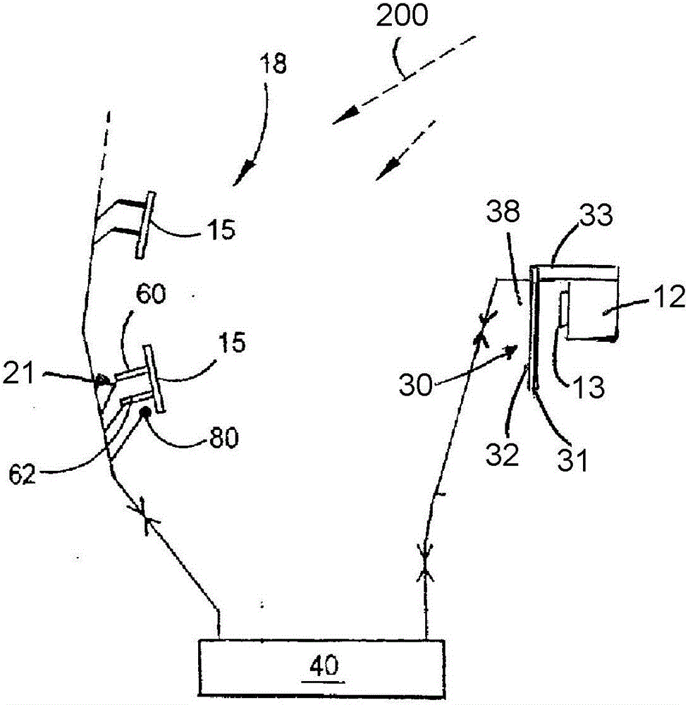
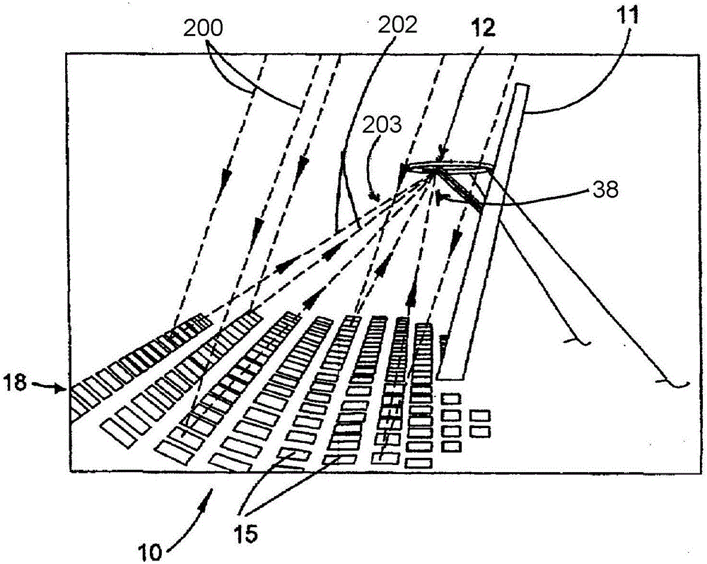
[0051] The invention has particular utility in the operation of central receiver solar energy collection systems utilizing economically manufactured heliostats. exist figure 1 An exemplary such system 10 is depicted in . The system includes a central solar receiver 12 mounted cantilevered from a tower 11 above or in front of a large array or field 18 of horizontally spaced heliostats 15 . Heliostats 15 are mounted for angular adjustment to optimally receive a respective beam of sunlight 200 and direct the beam (as a respective directed beam 202 ) to solar receiver 12 . as in figure 2 As best shown in , the receiver 12 has an aperture that defines a receiver target to receive a directed beam 202 of sunlight from the heliostats during operation of the system. The steered beams 202 together form a composite beam 203 incident on a receiver target.

[0052] The optimal receiving position in this context is the two-dimensional angular position of the heliostats at a specific ti...


PUM


Abstract

Described herein is an apparatus for monitoring and / or measuring multiple directional light radiative sources (15), each radiative source directing light radiation as a beam (202) of limited solid angle. The apparatus comprises a measuring device (33) having the capability to angularly distinguish the directional radiative sources from one another. The apparatus also includes means to scan the measuring device (33) across or through a zone on which at least 50% of the radiation beam from each radiative source impinges. The apparatus includes means (32) to record a set of multiple images respectively detected at the measuring device (33) at successive positions of the measuring device (33) during said scan. The radiation from the multiple directional radiative sources (15) is recorded at different positions of the measuring device (33) as the measuring device is scanned across the zone. The positions are sufficiently distinguishable in said set of multiple images to permit simultaneous measuring and / or monitoring of the directional radiative sources during a single scan of the measuring device (33) across or through said zone.

Description

technical field [0001] The present invention generally relates to monitoring and / or measuring the orientation of multiple directional light sources. The invention enables the measurement of ray angles and radiation intensities within an array of locations. One use is to simultaneously measure a pattern of intensities from each of multiple light sources. The invention is particularly, though not exclusively, useful in the calibration and control of heliostats for solar fields. Such solar fields can typically be of the kind that have a central solar receiver (usually on a pylon) and an array of heliostats mounted for angle adjustment to optimally receive the sunbeam and direct it to the central receiver solar energy harvesting device. Solar energy collection devices of the kind described above are referred to herein as central receiver solar energy collection systems. Background technique [0002] One challenge with central receiver solar collection systems is the trade-of...

Claims


Application Information

Patent Timeline
IPC IPC(8): F24J2/07F24J2/10F24J2/38F24J2/54F24S20/20F24S23/70F24S50/20
CPCF24S20/20F24S23/70F24S30/45F24S50/20F24S2050/25G02B7/183G02B7/198Y02E10/47
Inventor A.布顿M.科林斯
Owner COMMONWEALTH SCI & IND RES ORG
Why Eureka
Try Eureka