a centrifugal mechanism
A centrifugal mechanism and pawl technology, which is applied in vehicle parts, vehicle gearboxes, transportation and packaging, etc., can solve problems such as poor stability and complex structure, and achieve the effect of high stability, good stability and improved centrifugal force
- Summary
- Abstract
- Description
- Claims
- Application Information
AI Technical Summary
Problems solved by technology
Method used
Image
Examples
Embodiment 1
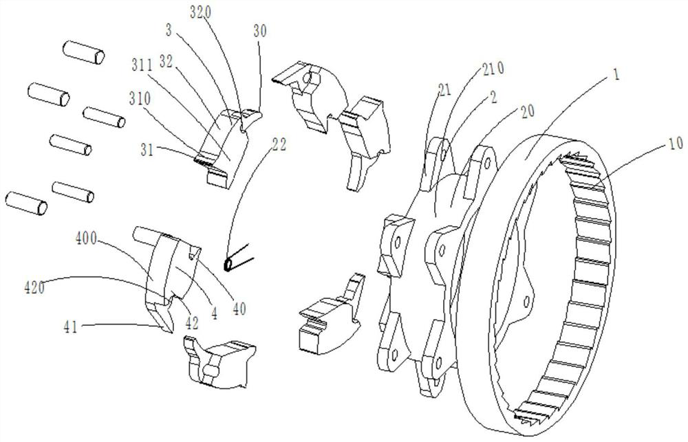
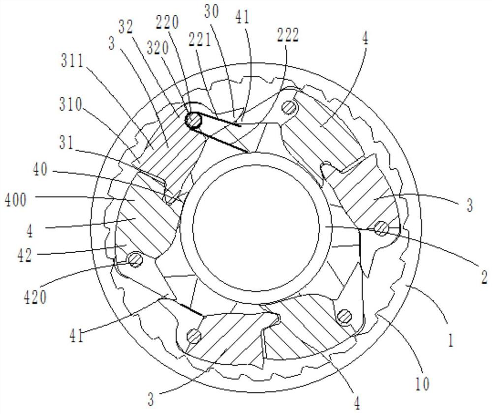
[0030] ginseng Figure 1 to Figure 3 As shown, the present invention discloses a centrifugal mechanism for automatic gear shifting, which is mainly composed of a ratchet wheel 1, a pawl fixing frame 2, three pawl parts 3 and three linkage parts 4, among which the three ratchet The pawl piece 3 and the three linkage pieces 4 are arranged between the ratchet wheel 1 and the pawl fixing frame 2 and are arranged at intervals in the circumferential direction, that is, a linkage piece 4 is arranged between every two adjacent pawl pieces 3 .
[0031] The ratchet 1 is located on the outside of the ratchet holder 2 , and ratchets 10 are arranged on the inner peripheral surface of the ratchet 1 .
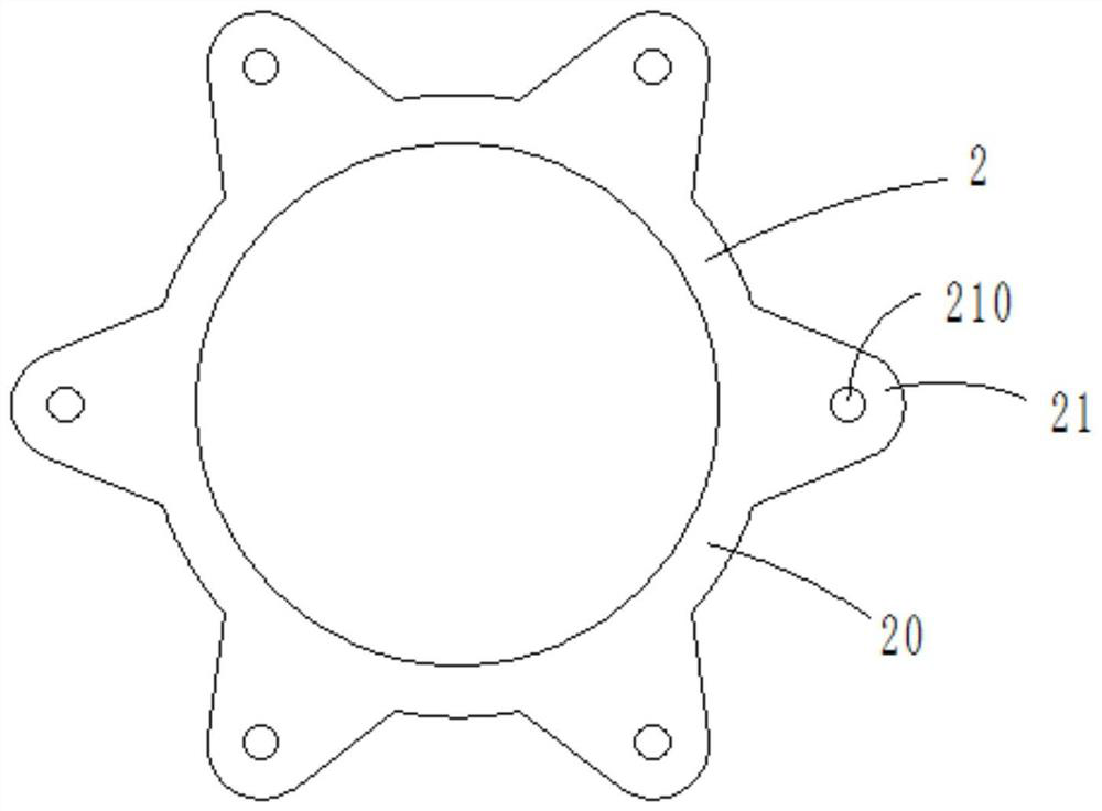
[0032] The pawl fixing frame 2 includes an annular base 20 and several mounting seats 21 extending outward from the outer wall of the annular base 20. The mounting seats 21 are provided with pin holes 210 for mounting pins. The mounting seat 21 is provided with a torsion spring 22 for contro...
Embodiment 2
[0038] ginseng Figure 4 As shown, the rest of the structure of the centrifugal mechanism in this embodiment is the same as that of Embodiment 1, except that in Embodiment 1, the third end 40 of the linkage member 4 is limited to the pawl member 3 along the radial direction. Inside the second end portion 31, the fourth end portion 41 of the linkage member 4 is limited to the inner side of the first end portion 30 of the pawl member 3 along the radial direction, and in this embodiment, the pawl along the radial direction The second end 31 of the component 3 is limited inside the third end 40 of the linkage component 4 , and the first end 30 of the pawl component 3 is limited inside the fourth end 41 of the linkage component 4 along the radial direction. In this embodiment, the circular installation part 220 is installed on the pin in the second installation hole 420, and the first torsion bar 221 gives the first end 30 of the ratchet member 3 outward from the center of the circ...
Embodiment 3
[0041] refer to Figure 5 As shown, the other structural principles of the centrifugal mechanism in this embodiment are the same as those in Embodiment 1, the difference being that the centrifugal mechanism in Embodiment 1 mainly consists of a ratchet wheel 1, a ratchet holder 2, and three ratchet parts. 3 and three linkages 4 are composed of several parts, wherein three pawls 3 and three linkages 4 are arranged between the ratchet 1 and the pawl holder 2, and are arranged at intervals in the circumferential direction, that is, every two A linkage piece 4 is arranged between adjacent pawl pieces 3 . The centrifugal mechanism in this embodiment is mainly composed of a ratchet 1, a pawl fixing frame 2, a torsion spring 22, two pawl parts 3 and a linkage part 4, wherein two pawl parts 3 and a linkage part 4 and the torsion spring 22 are all arranged between the ratchet 1 and the pawl fixing frame 2, and are arranged at intervals in the circumferential direction, that is, the tor...
PUM
 Abstract
Description
Claims
Application Information
 - R&D
- Intellectual Property
- Life Sciences
- Materials
- Tech Scout
- Unparalleled Data Quality
- Higher Quality Content
- 60% Fewer Hallucinations
Browse by: Latest US Patents, China's latest patents, Technical Efficacy Thesaurus, Application Domain, Technology Topic, Popular Technical Reports.
© 2025 PatSnap. All rights reserved.Legal|Privacy policy|Modern Slavery Act Transparency Statement|Sitemap|About US| Contact US: help@patsnap.com


