Electronic expansion valve

An electronic expansion valve, valve seat technology, applied in the direction of lift valve, valve details, valve device, etc., can solve the problems of electronic expansion valve noise, liquid medium easily mixed with air, etc.

Active Publication Date: 2017-03-29
DUNAN ENVIRONMENT TECH
View PDF7 Cites 10 Cited by
  • Summary
  • Abstract
  • Description
  • Claims
  • Application Information

AI Technical Summary

Problems solved by technology

However, when the liquid medium flows into the guide sleeve from the valve port, air is easily mixed into the liquid

Method used


Image

  • Electronic expansion valve
  • Electronic expansion valve
  • Electronic expansion valve

Examples


Embodiment 1

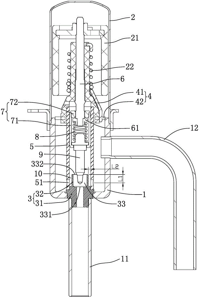
[0025] refer to figure 1 , an electronic expansion valve, comprising a valve body, a valve needle 9, a valve seat 3 and a driving mechanism, the valve seat 3 is arranged at the lower end of the valve body, the valve seat 3 is provided with a valve port 331, the driving mechanism is arranged at the upper end of the valve body, and the valve The needle 9 is connected to the driving mechanism and is driven by the driving mechanism to open or close the valve port 331. The valve body is also provided with a guide sleeve 5 for guiding the axial movement of the valve needle 9. The guide sleeve 5 is provided with a number of side wall through holes 51. , considering the manufacturing cost, the side wall through holes 51 are substantially evenly distributed on the guide sleeve 5 .

[0026] refer to figure 1 Specifically, the electronic expansion valve further includes a nut assembly 4 , the nut assembly 4 includes a nut 41 and a connecting piece 42 , the nut 41 is covered with a limit...

Embodiment 2

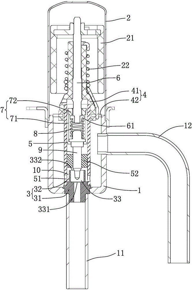
[0035] refer to figure 2 , an electronic expansion valve, comprising a valve body, a valve needle 9, a valve seat 3 and a driving mechanism, the valve seat 3 is arranged at the lower end of the valve body, the valve seat 3 is provided with a valve port 331, the driving mechanism is arranged at the upper end of the valve body, and the valve The needle 9 is connected to the driving mechanism and is driven by the driving mechanism to open or close the valve port 331. The valve body is also provided with a guide sleeve 5 for guiding the axial movement of the valve needle 9. The guide sleeve 5 is provided with a number of side wall through holes 51. , considering the manufacturing cost, the side wall through holes 51 are substantially evenly distributed on the guide sleeve 5 .

[0036] refer to figure 2 Specifically, the electronic expansion valve further includes a nut assembly 4 , the nut assembly 4 includes a nut 41 and a connecting piece 42 , the nut 41 is covered with a lim...

Embodiment 3

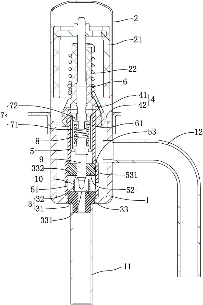
[0041] refer to image 3 , an electronic expansion valve, comprising a valve body, a valve needle 9, a valve seat 3 and a driving mechanism, the valve seat 3 is arranged at the lower end of the valve body, the valve seat 3 is provided with a valve port 331, the driving mechanism is arranged at the upper end of the valve body, and the valve The needle 9 is connected to the driving mechanism and is driven by the driving mechanism to open or close the valve port 331. The valve body is also provided with a guide sleeve 5 for guiding the axial movement of the valve needle 9. The guide sleeve 5 is provided with a number of side wall through holes 51. , considering the manufacturing cost, the side wall through holes 51 are substantially evenly distributed on the guide sleeve 5 .

[0042] refer to image 3 Specifically, the electronic expansion valve further includes a nut assembly 4 , the nut assembly 4 includes a nut 41 and a connecting piece 42 , the nut 41 is covered with a limit...


PUM


Abstract

The invention relates to an electronic expansion valve. The problem that electronic expansion valves are high in noise is solved. The electronic expansion valve comprises a valve body, a valve needle, a valve seat and a driving mechanism. The valve is arranged at the lower end of the valve body. A valve port is formed in the valve seat. The driving mechanism is arranged at the upper end of the valve body. The valve needle is connected with the driving mechanism and driven by the driving mechanism to open or close the valve port. A guiding sleeve used for guiding the valve needle to move axially is further arranged in the valve body and provided with a plurality of side wall through holes. An annular flow channel is formed between the outer side wall of the valve seat and the inner wall of the guiding sleeve. The side wall through holes are evenly distributed in the guiding sleeve mainly and correspond to the annular flow channel.

Description

technical field [0001] The invention relates to the field of refrigeration equipment, in particular to an electronic expansion valve used in refrigeration equipment. Background technique [0002] Electronic expansion valve is an important part of refrigeration equipment, which mainly plays the role of throttling and reducing pressure and regulating flow. The existing electronic expansion valve includes a valve body, a valve seat and a guide sleeve. The valve seat is provided with a valve port, the guide sleeve is provided with a number of side wall through holes, and the guide sleeve is provided with a valve core assembly. The valve core assembly includes a valve needle. When the valve needle opens the valve port, the liquid medium flows into the guide sleeve from the valve port and flows through the side wall through hole. However, when the liquid medium flows into the guide sleeve from the valve port, air is easily mixed into the liquid medium, thereby generating air bubb...

Claims


Application Information

Patent Timeline
IPC IPC(8): F16K1/00F16K1/42F16K47/02F25B41/06F25B41/34
CPCF16K1/00F16K1/42F16K47/02F25B41/34F25B41/31Y02B30/70
Inventor 陈娟王定军苏鹏
Owner DUNAN ENVIRONMENT TECH
Why Eureka
Try Eureka