Steam lock relieving device of steam system drain valve

A steam system and steam trap technology, which is applied in the direction of steam traps, mechanical equipment, etc., can solve the problems of increased drying time, low energy utilization rate, and large steam consumption, so as to reduce steam consumption and improve energy consumption. Utilization rate, the effect of improving the heat exchange effect

Active Publication Date: 2017-03-29
常州宏大智慧科技有限公司
View PDF8 Cites 7 Cited by
  • Summary
  • Abstract
  • Description
  • Claims
  • Application Information

AI Technical Summary

Problems solved by technology

However, in the actual working process, the steam trap and the ball float trap are filled with high-temperature steam, and the temperature is much higher than 80 degrees. The steam lock release device of the valve cannot release the steam in the drain pipe in time, that is, the steam lock cannot be released in time, causing the condensed water in the steam transmission pipeline and the steam drying cylinder to be locked by the steam lock and cannot be discharged through the float trap. There are potential safety hazards; condensed water cannot be discharged, which affects the heat exchange effect of the dryer, increases the drying time, consumes a lot of steam, lowers energy utilization, increases operating costs, and affects production capacity.

Method used


Image

  • Steam lock relieving device of steam system drain valve
  • Steam lock relieving device of steam system drain valve
  • Steam lock relieving device of steam system drain valve

Examples


Embodiment 1

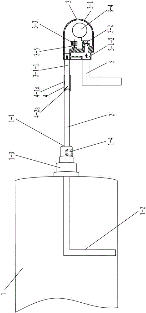
[0029] Such as figure 1 , 5 As shown, a steam system steam trap release steam lock device, including steam drying cylinder 1, siphon 1-2, steam rotary joint 1-3, steam trap 2 and steam trap 3, said steam drying cylinder 1 is equipped with steam rotary Joint 1-3, one end of steam rotary joint 1-3 is connected with one end of siphon pipe 1-2, the other end is connected with one end of drain pipe 2, and one end of drain pipe 2 is connected with siphon pipe 1-2 through steam rotary joint 1-1 The other end is connected with the water inlet 3-1-1 of the steam trap 3, the steam trap 3 also has a water outlet 3-1-2, and the steam rotary joint 1-1 has a steam inlet 1-4; A steam lock release mechanism 4 is provided on the pipeline of the pipe 2, and the steam lock release mechanism 4 is arranged between the steam rotary joint 1-3 of the steam drying cylinder 1 and the steam trap 3.

[0030] Such as figure 1 , 5 As shown, the steam lock release mechanism 4 includes a connecting sleev...

Embodiment 2

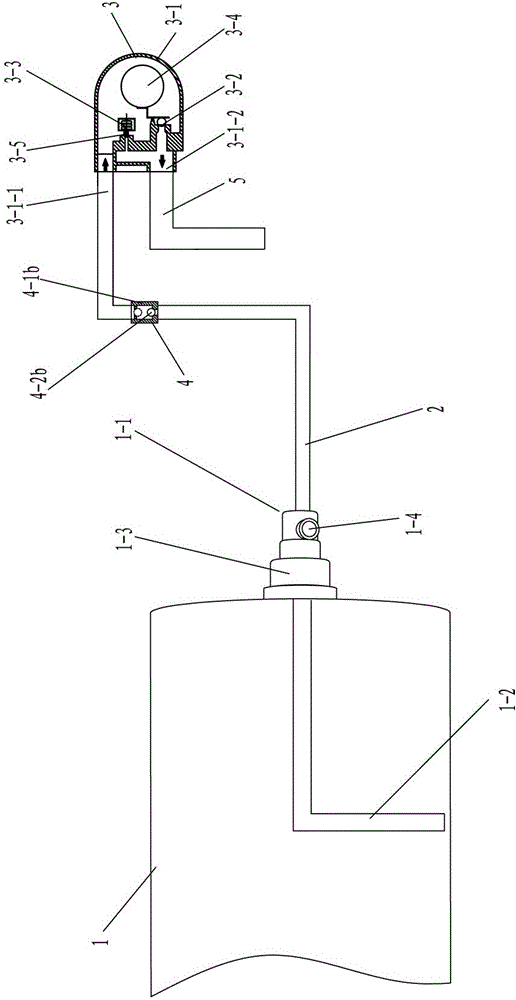
[0036] Such as figure 2 , 6 , 7, the difference between embodiment 2 and embodiment 1 is that: the steam lock release mechanism 4 includes a connecting pipe 4-1b and a sphere 4-2b, and the connecting pipe 4-1b is arranged on the pipe of the drain pipe 2 On the road, and the angle α between the axis OG of the connecting pipe 4-1b and the center of gravity line OQ of the sphere 4-2b is 0°≤α≤85°, and the diameters at both ends of the connecting pipe 4-1b are smaller than the diameter of the sphere 4-2b , The ball 4-2b is located in the connecting pipe 4-1b.

[0037] The working process of embodiment 2 is: when the equipment of steam dryer 1 has just started to work, the internal temperature of the float trap 3 is less than 70 degrees, and the built-in steam lock release device of the float trap 3 is in the enabled state, and its The exhaust valve opens. Since the exhaust valve is open at this time, the steam greater than the atmospheric pressure of the air enters the steam dr...

Embodiment 3

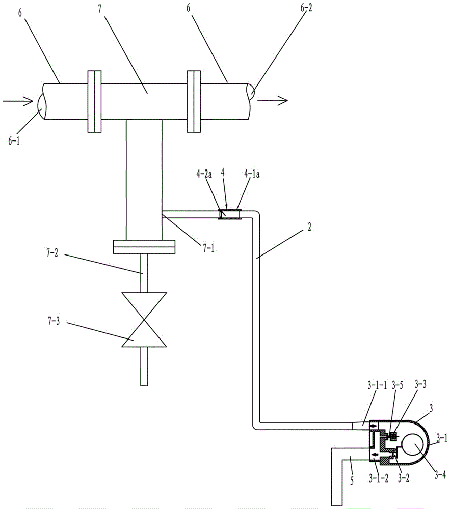
[0040] Such as image 3 , 5 As shown, a device for steam trap release in a steam system has a steam transmission pipeline 6, a pipeline tee 7, a steam trap 2 and a steam trap 3, and the steam trap 3 has a water inlet 3-3-1 and an outlet The water port 3-1-2, the pipeline tee 7 has a drain port 7-1, the water inlet 3-3-1 of the drain valve 3 is connected with one end of the drain pipe 2, and the other end of the drain pipe 2 is connected with the pipeline The drain port 7-1 of the tee 7 is connected, the pipeline of the drain pipe 2 is provided with a steam lock release mechanism 4, and the steam lock release mechanism 4 is provided with a pipeline tee 7 and a steam trap 3 of the steam transmission pipeline 6 between.

[0041] The steam lock release mechanism 4 includes a connecting sleeve 4-1a and a baffle 4-2a, the connecting sleeve 4-1a is arranged on the pipeline of the drain pipe 2, and the baffle 4-2a is arranged on the connecting sleeve 4-1a in the nozzle or pipe, and...


PUM


Abstract

The invention relates to a steam lock relieving device of a steam system drain valve. The device comprises a steam drying cylinder, a siphon pipe, a steam rotating joint, a drain pipe and a drain valve; a steam rotating joint is mounted on the steam drying cylinder; one end of the steam rotating joint is connected with one end of the siphon pipe, and the other end is connected with one end of the drain pipe; one end of the drain pipe is communicated with the siphon pipe through the steam rotating joint, and the other end is communicated with a water inlet of the drain valve; the drain valve has a water outlet; and the steam rotating joint has a steam inlet. The device is characterized in that a steam lock relieving mechanism is arranged on a pipeline of the siphon pipe or the drain pipe. The device can automatically stop steam from flowing to the drain valve to lower the internal temperature of the drain valve in the non-drain period, and can automatically relieve the stop in the drain period to timely enable the drain valve to carry with the steam lock relieving device to relieve the steam lock so as to drain condensed water continuously generated in the steam drying cylinder.

Description

technical field [0001] The invention specifically relates to a device for releasing steam locks of steam traps in a steam system, belonging to the technical field of textile dyeing and finishing. Background technique [0002] At present, when textile printing and dyeing enterprises use steam as a heat source to exchange heat with the object to be heated, condensed water will continue to be generated from the steam transmission pipeline to the steam at the steam end to exchange heat with the object to be heated. The accumulation of condensed water in the steam transmission pipeline will not only fail to obtain unsaturated steam at the steam end, but also cause water hammer accidents; when using a steam dryer to dry fabrics with water, due to the steam dryer and belt Water fabrics are used for heat exchange, but condensed water will continue to be generated in the steam dryer, which will easily form water hammer, aggravate the wear of pipe walls, valves and joints, increase ma...

Claims


Application Information

Patent Timeline
Patent Type & Authority Applications(China)
IPC IPC(8): F16T1/38F16T1/02
CPCF16T1/02F16T1/38
Inventor 顾金华
Owner 常州宏大智慧科技有限公司
Why Eureka
Try Eureka