Split type air cooling type constant temperature and humidity air conditioner

A constant temperature and humidity, air conditioner technology, applied in refrigerators, air conditioning systems, compressors with multiple condensers, etc., can solve problems such as unreliable operation, overcurrent, fire, etc., and achieve the goal of improving safety and reliability Effect

Inactive Publication Date: 2017-03-29
GUANGDONG SHENLING ENVIRONMENT SYST CO LTD
View PDF9 Cites 11 Cited by
  • Summary
  • Abstract
  • Description
  • Claims
  • Application Information

AI Technical Summary

Problems solved by technology

However, due to the general air-cooled constant temperature and humidity air conditioner, the reheating and temperature adjustment are all completed by electric heating, and most of the compressors work under the condition of constant frequency. , the cooling capacity of the compressor is too large, and the air outlet temperature of the air conditioner is significantly lower than the set temperature and humidity requirements. A large amount of electric heating is required to achieve thermal compensation and ensure constant temperature and humidity. Although this method can achieve constant temperature and humidity purpose, but consumes a lot of energy
Taking an existing 25kW constant temperature and humidity air conditioning unit as an example, in addition to electric heating, the rated power of the whole machine is only 10kW, but it needs to be equipped with 18kW reheat electric heating capacity, which is twice that of the air conditioner, and the energy consumption Very huge, high energy consumption, and the operation of high-power electric heaters is prone to problems such as overheating, overcurrent, burning, and even fire, and the operation is unreliable

Method used


Image

  • Split type air cooling type constant temperature and humidity air conditioner
  • Split type air cooling type constant temperature and humidity air conditioner

Examples


Embodiment Construction

[0019] The present invention provides a split-flow air-cooled constant temperature and humidity air conditioner. In order to make the objectives, technical solutions and effects of the present invention clearer and clearer, the present invention will be further described in detail below with reference to the drawings and embodiments. It should be understood that the specific embodiments described here are only used to explain the present invention, but not to limit the present invention.

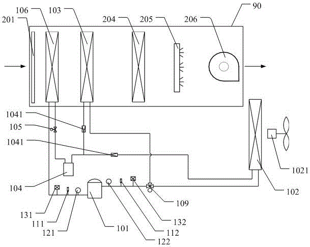
[0020] See figure 1 , The present invention provides a split air-cooled constant temperature and humidity air conditioner, figure 1 The "90" is used to indicate the air circulation channel in the air conditioner, and the purpose is to express the arrangement sequence of the various components in the channel. figure 1 The direction of the arrow in is the flow direction of the circulating air.

[0021] The split-flow air-cooled constant temperature and humidity air conditioner includes a casing (not...


PUM


Abstract

The invention discloses a split type air cooling type constant temperature and humidity air conditioner. The air conditioner comprises a shell, a compressor, a reheating condenser, an expansion valve, an evaporator, a humidifier, an air supply fan, an air cooling condenser and a corresponding condensation fan, wherein the compressor, the reheating condenser, the expansion valve and the evaporator are arranged in the shell and circularly connected in sequence, the humidifier is arranged in the shell, the air supply fan is arranged in an air supply outlet of the air conditioner, and the air cooling condenser and the corresponding condensation fan are arranged outdoors. An inlet of the reheating condenser and an inlet of the air cooling condenser are connected with an air outlet of the compressor through a three-way proportional control valve. An outlet of the reheating condenser and an outlet of the air cooling condenser are connected with an inlet of the expansion valve in parallel. The split type air cooling type constant temperature and humidity air conditioner effectively utilizes heat produced in a refrigerant circulation process for heating air, achieves the purposes of energy conservation and environment protection and meanwhile further has the advantages of being easy to adjust, high in reliability and the like.

Description

Technical field [0001] The invention relates to the field of air conditioners, in particular to a split-flow air-cooled constant temperature and humidity air conditioner. Background technique [0002] The existing air-cooled constant temperature and humidity air conditioner uses an evaporator to cool down and dehumidify, through electric heating and reheating to adjust the temperature, and then through a humidifier to adjust the humidity to meet the requirements of air-conditioned rooms with special requirements for temperature and humidity, and provide constant temperature and humidity air deal with. However, due to the general air-cooled constant temperature and humidity air conditioner, the reheating and temperature adjustment are all completed by electric heating, and the compressor works under fixed frequency conditions in most cases. When the compressor is fully opened, under partial load conditions , The cooling capacity of the compressor is too large, and the air outlet ...

Claims


Application Information

Patent Timeline
Patent Type & Authority Applications(China)
IPC IPC(8): F24F5/00F24F11/02F24F11/00F25B6/02F25B49/02
CPCF24F5/001F24F11/0008F24F2221/34F25B6/02F25B49/022F24F11/30F24F11/70F24F11/89F24F2110/10F24F2110/20
Inventor 林创辉谢永健陆思荣刘孟容梁小盈林水荣黄伯伟
Owner GUANGDONG SHENLING ENVIRONMENT SYST CO LTD
Why Eureka
Try Eureka