Method for measuring spring stiffness of supporting and hanging frame online
A technology of spring stiffness and support and hanger, which is applied in the field of measurement, can solve problems such as loss of load, inability to adjust, overload of support and hanger, etc., and achieve the effect of simple and convenient data, fast measurement and accurate data
- Summary
- Abstract
- Description
- Claims
- Application Information
AI Technical Summary
Problems solved by technology
Method used
Image

Examples
Embodiment Construction
[0022] The present invention will be further described below in conjunction with accompanying drawing.
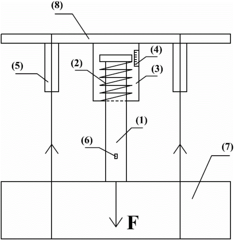
[0023] figure 1 The shown support and hanger includes the support and hanger sleeve 3 fixed on the steel frame 8, the support and hanger pull rod 1 installed in the support and hanger sleeve, the briquetting block arranged on the top of the support and hanger pull rod and the The spring 2 at the lower end of the briquetting block and the load F brought by the pipeline 7 act on the steel frame through the hanger pull rod, the spring and the hanger sleeve in turn.
[0024] In the present invention, a strain gauge 6 for measuring the strain of the pull rod is installed on the pull rod of the support and hanger. When the pull rod is stretched downward due to the weight of the pipeline, the strain gauge outputs and records the strain data of the pull rod. The two sides of the support and hanger sleeve are respectively equipped with a lifting hoist 5 installed on the steel frame...
PUM
 Abstract
Description
Claims
Application Information
 - R&D
- Intellectual Property
- Life Sciences
- Materials
- Tech Scout
- Unparalleled Data Quality
- Higher Quality Content
- 60% Fewer Hallucinations
Browse by: Latest US Patents, China's latest patents, Technical Efficacy Thesaurus, Application Domain, Technology Topic, Popular Technical Reports.
© 2025 PatSnap. All rights reserved.Legal|Privacy policy|Modern Slavery Act Transparency Statement|Sitemap|About US| Contact US: help@patsnap.com