Lifting chain single-ring bending force testing machine

A technology of bending force and testing machine, which is applied in the testing of mechanical components, testing of machine/structural components, testing of machine gears/transmission mechanisms, etc. It can solve problems such as strength testing, failure to know potential safety hazards, chain links, etc., and improve stability Sexuality, reduction of labor intensity, and efficient effect of trial pulling

Active Publication Date: 2017-03-29
ZHEJIANG SHUANGNIAO MACHINERY
View PDF9 Cites 0 Cited by
  • Summary
  • Abstract
  • Description
  • Claims
  • Application Information

AI Technical Summary

Problems solved by technology

[0004] The lifting chain is composed of multiple individual chain links (chain links) connected with each other. When the hoist is used in actual working conditions, each link on the chain needs to bear the gravity of the heavy object. At present, the safety of the finished chain is considered. The best method is to use the whole chain on the bar pulling equipment to test the chain before leaving the factory by manpower. The whole chain of a hoist with one specification has a total length as short as 2.5 meters and as long as tens of meters. Therefore, it is impossible to know the links that may have potential safety hazards. In view of the disadvantages of conventional test equipment, how to design a chain-by-link strength testing equipment is really a challenge for the chain manufacturing industry. Directions that need to be worked on

Method used


Image

  • Lifting chain single-ring bending force testing machine
  • Lifting chain single-ring bending force testing machine
  • Lifting chain single-ring bending force testing machine

Examples


Embodiment Construction

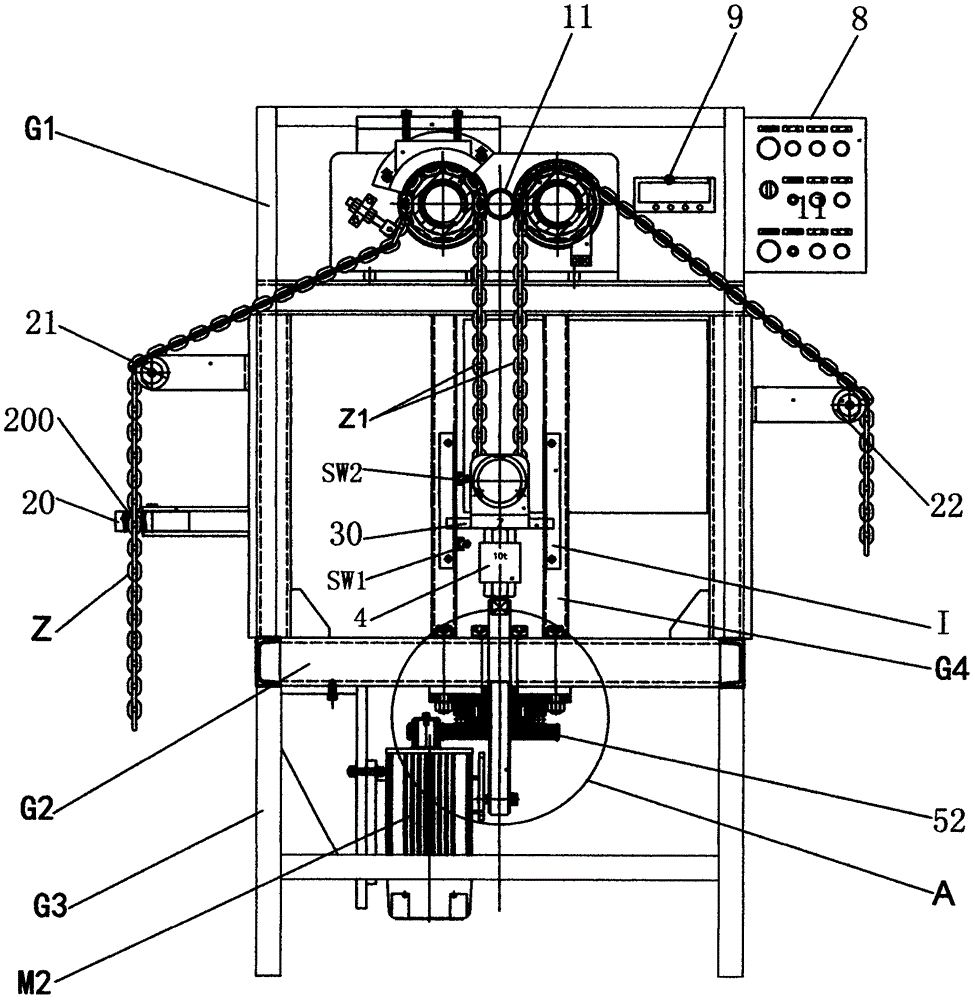
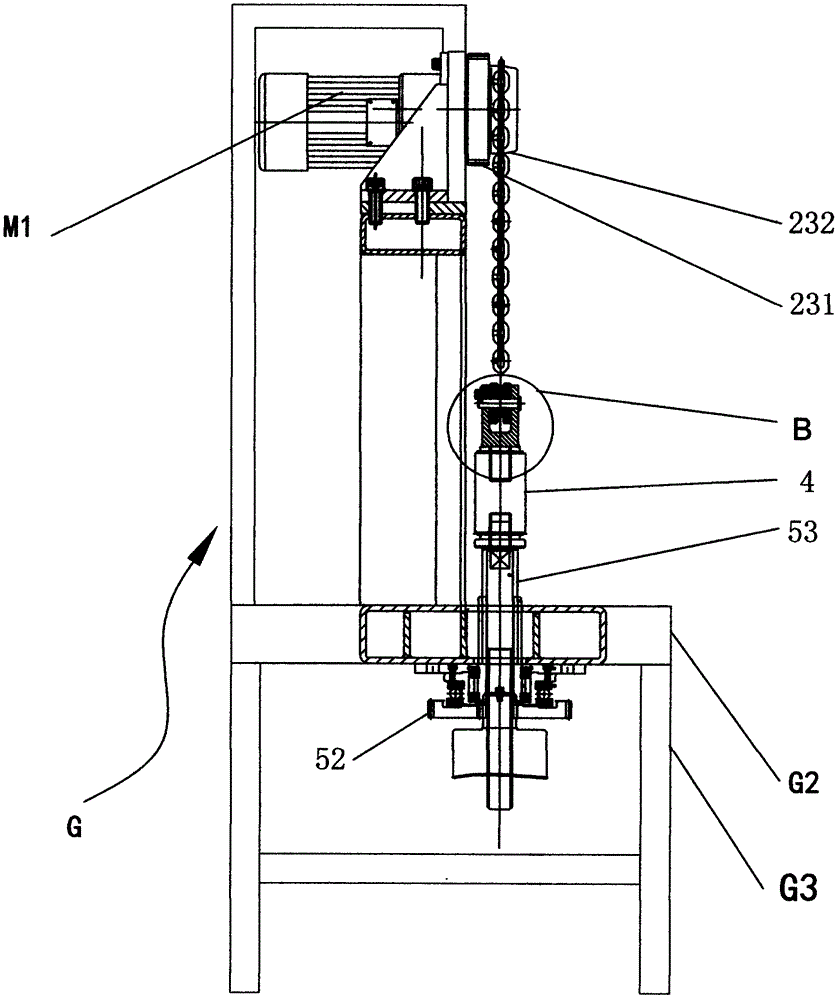
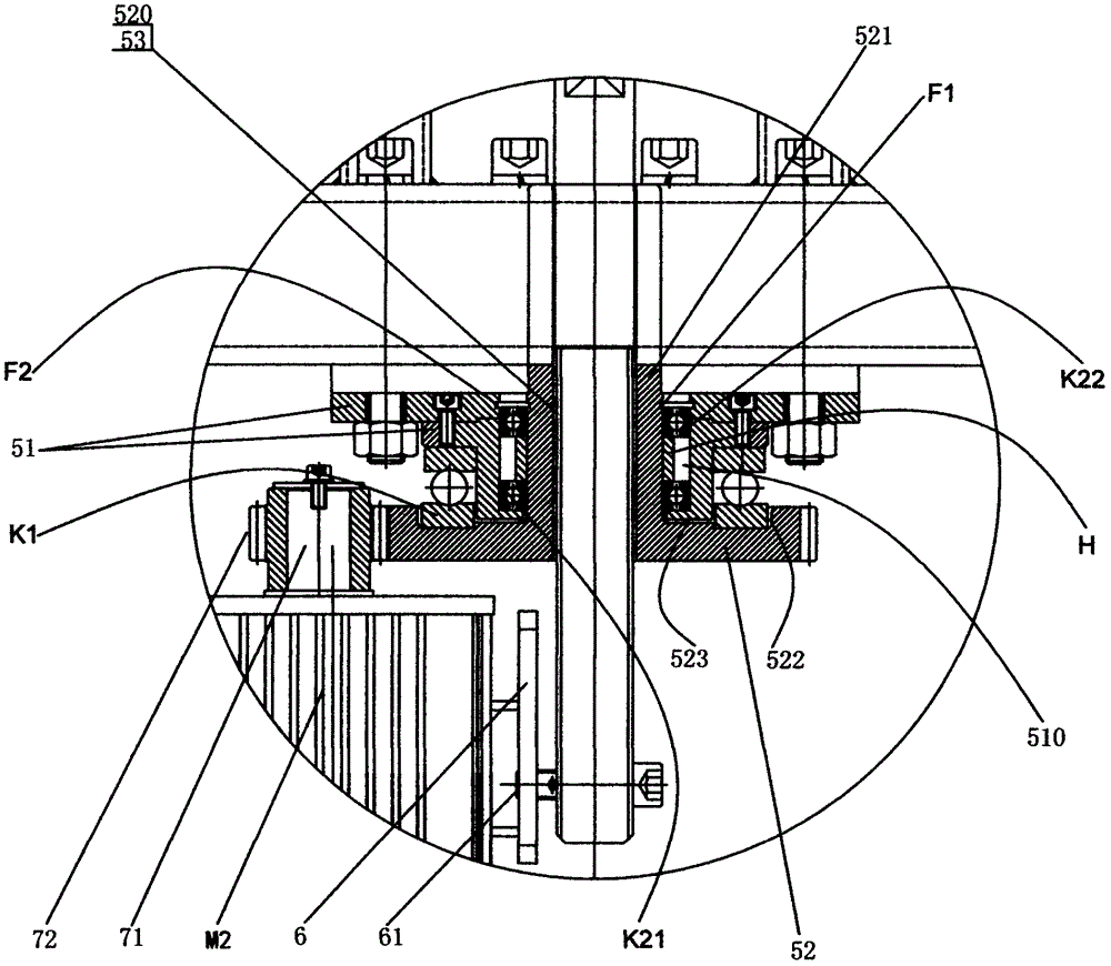
[0026] see figure 1 , 2 , 3, 4, 5, 6, and 7 show preferred embodiments of the present invention.

[0027] The lifting chain single-ring bending force testing machine includes the fuselage G, the chain transmission mechanism and the driving device of the chain transmission mechanism. A chain drive motor M1 with a central pinion 11 on the upper part of the body G1, the chain drive mechanism includes a chain-in guide wheel 21 located on one side of the fuselage G, and a chain-out guide wheel 21 located on the other side of the fuselage G. The guide wheel 22 and the input chain shaft wheel assembly 23 and the output chain shaft wheel assembly 24 respectively arranged on the upper part G1 of the fuselage, the middle pinion 11 meshes with the input chain shaft wheel assembly 23 and the output chain shaft wheel assembly 24 respectively, and is rotated on the cruise ship The cruise ship 31 on the seat 3 meshes with the double-row chain Z1, and the cruise ship 31 suspended by the dou...


PUM


Abstract

The invention discloses a lifting chain single-ring bending force testing machine. The lifting chain single-ring bending force testing machine comprises a chain walking transmission mechanism and a lifting and speed reduction mechanism; the chain walking transmission mechanism includes a chain incoming guide wheel and a chain outgoing guide wheel which are located at two sides of a machine body in a split manner as well as a chain incoming axle wheel assembly and a chain outgoing axle wheel assembly which are arranged on the machine body in a split manner; the chain incoming axle wheel assembly and the chain outgoing axle wheel assembly are both engaged with a centrally-installed pinion in a chain walking driving motor installed at the upper portion of the machine body; a loose pulley is suspended by a double-row chain; a torque sensor is fixed to the lower end of a loose pulley holder; the lifting and speed reduction mechanism includes a chassis, a transmission large gear and a screw rod; the chassis is fixed at the bottom of the platen of the machine body; a stepped hole is formed in the chassis; a central screw hole formed in the large gear is in transmission engagement with the screw rod; a necking section at the upper end of the central screw hole, which extends axially, is limited in the stepped hole; the top end of the screw rod extends out from the necking section and fixes the torque sensor; a guide short shaft fixedly arranged at the bottom end of the screw rod is arranged in the guide hole of a guide fixed plate in a sliding manner; and the transmission large gear is engaged with the output pinion of the output shaft of a lifting motor. The lifting chain single-ring bending force testing machine can test the strength of the double-row chain through bending, pulling and tensioning.

Description

[0001] 【Technical field】 [0002] The invention relates to a single-ring bending force testing machine for a lifting chain, which belongs to the technical field of testing the safety load loading force of finished lifting chains. [0003] 【Background technique】 [0004] The lifting chain is composed of multiple individual chain links (chain links) connected with each other. When the hoist is used in actual working conditions, each link on the chain needs to bear the gravity of the heavy object. At present, the safety of the finished chain is considered. The best method is to use the whole chain on the bar pulling equipment to test the chain before leaving the factory by manpower. The whole chain of a hoist with one specification has a total length as short as 2.5 meters and as long as tens of meters. Therefore, it is impossible to know the links that may have potential safety hazards. In view of the disadvantages of conventional test equipment, how to design a chain-by-link str...

Claims


Application Information

Patent Timeline
Patent Type & Authority Applications(China)
IPC IPC(8): G01M13/02
CPCG01M13/023G01M13/027Y02E30/30
Inventor 盛嘉庆叶小江竺春钢单伟军竹敬南
Owner ZHEJIANG SHUANGNIAO MACHINERY
Why Eureka
Try Eureka