Low-frequency broadband high-efficiency low-profile back-cavity antenna

A low-profile, broadband technology, applied in the direction of slot antenna, antenna grounding switch structure connection, radiation element structure, etc., can solve the problems of poor reliability and manufacturability, inconvenient installation and use, and large vertical size of antenna, etc., to achieve Small impact, improve structural strength, avoid the effect of cantilever structure

Active Publication Date: 2017-03-29
SOUTHWEST CHINA RES INST OF ELECTRONICS EQUIP
View PDF4 Cites 7 Cited by
  • Summary
  • Abstract
  • Description
  • Claims
  • Application Information

AI Technical Summary

Problems solved by technology

The logarithmic antenna is easily affected by the installation platform, and its longitudinal dimension is large; the horn antenna is similar to the logarithmic antenna, and the low-frequency antenna has a large longitudinal dimension, which is not easy to install and use
The dipole antenna can be added with a back cavity to reduce the impact of the platform, but the work efficiency is low, and the reliability and manufacturability are poor
For application platforms that require low frequency, broadband, low profile, high efficiency, and high reliability, existing technologies cannot meet the requirements

Method used


Image

  • Low-frequency broadband high-efficiency low-profile back-cavity antenna
  • Low-frequency broadband high-efficiency low-profile back-cavity antenna
  • Low-frequency broadband high-efficiency low-profile back-cavity antenna

Examples


Embodiment Construction

[0025] All features disclosed in this specification, or steps in all methods or processes disclosed, may be combined in any manner, except for mutually exclusive features and / or steps.

[0026] Any feature disclosed in this specification, unless specifically stated, can be replaced by other alternative features that are equivalent or have similar purposes. That is, unless expressly stated otherwise, each feature is one example only of a series of equivalent or similar features.

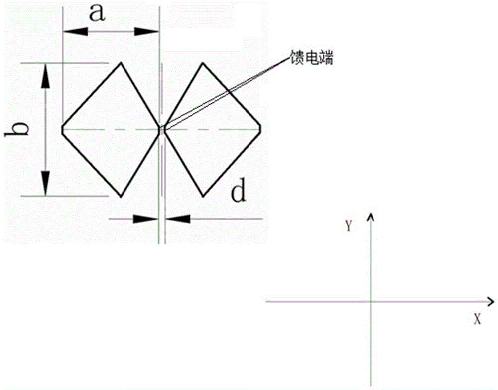
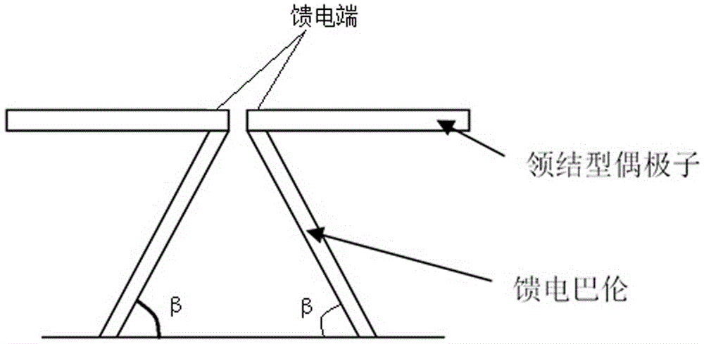
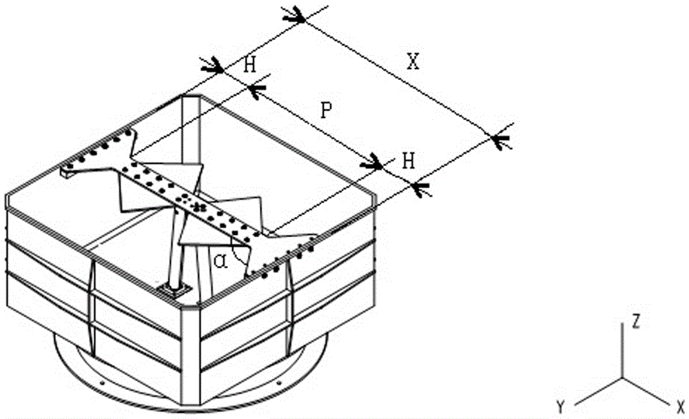
[0027] A low-frequency broadband high-efficiency low-profile cavity-backed antenna includes a bow-tie-shaped dipole, a feed balun, a reflective cavity with an opening on the top surface, and an H-shaped dielectric rod; the two ends of the H-shaped dielectric rod are respectively opposite to the open end faces of the reflective cavity Both sides are connected; the feed balun is built into the reflection cavity, and the cavity connection end of the feed balun is connected to the bottom surface of the re...


PUM


Abstract

The present invention belongs to the back-cavity antenna design field and provides a low-frequency broadband high-efficiency low-profile back-cavity antenna. The objective of the invention is to solve problems in the prior art. According to the low-frequency broadband high-efficiency low-profile back-cavity antenna of the invention, a bow tie-shaped dipole and a feed Balun are arranged in a reflection cavity; the root portion of the feed Balun is connected with the bottom end surface of the reflection cavity; the top end of the feed Balun is connected with the feed end surface of the tie-shaped dipole; the other end surface of the tie-shaped dipole is connected with an H-shaped medium pull rod; the cavity connection end of the feed Balun is a connection port which is connected with the bottom end surface of the reflection cavity; the end surface of the cavity connection end of the feed Balun is parallel to the bottom surface of the reflection cavity; the dipole connection end of the feed Balun is a connection end which is infinitely closed to the feed end of the tie-shaped dipole; the end surface of the dipole connection end of the feed Balun is parallel to the bottom surface of the reflection cavity; and two ends of the H-shaped medium pull rod are respectively connected with two opposite edges of the opening end surface of the reflection cavity.

Description

technical field [0001] The invention relates to the field of cavity-backed antenna design, in particular to a low-frequency, broadband, high-efficiency, low-profile cavity-backed antenna. Background technique [0002] An antenna with a working bandwidth of 2.5 times frequency can be realized by using various broadband antenna forms such as logarithmic, horn, and dipole. The logarithmic antenna is easily affected by the installation platform and has a large longitudinal dimension; the horn antenna is similar to the logarithmic antenna, and the low-frequency antenna has a large longitudinal dimension, which is not easy to install and use. The dipole antenna can be added with a back cavity to reduce the impact of the platform, but the work efficiency is low, and the reliability and manufacturability are poor. For application platforms that require low frequency, broadband, low profile, high efficiency, and high reliability, existing technologies cannot meet the requirements. ...

Claims


Application Information

Patent Timeline
Patent Type & Authority Applications(China)
IPC IPC(8): H01Q1/38H01Q1/50H01Q13/18
Inventor 叶君永朱海冰何亚东王雄柏京
Owner SOUTHWEST CHINA RES INST OF ELECTRONICS EQUIP
Why Eureka
Try Eureka