Carbonate rock area pulling-resistant anchor rod grouting and drainage device and construction method thereof

A carbonate rock and drainage device technology, applied in protection devices, foundation structure engineering, sheet pile walls, etc., can solve problems such as the difficulty of grouting anti-floating anchor rods, and achieve reduced grouting difficulty, low cost, and easy operation Effect

Inactive Publication Date: 2017-04-05
ZHENGYE ENG & INVESTMENT INC
View PDF6 Cites 4 Cited by
  • Summary
  • Abstract
  • Description
  • Claims
  • Application Information

AI Technical Summary

Problems solved by technology

[0004] The technical problem to be solved by the present invention is to provide a grouting drainage device for anti-lift bolts in carbonate rock areas and its construction method, so as to solve the problem of difficult grouting for anti-floating anchor rods in carbonate rock areas due to high water pressure

Method used


Image

  • Carbonate rock area pulling-resistant anchor rod grouting and drainage device and construction method thereof
  • Carbonate rock area pulling-resistant anchor rod grouting and drainage device and construction method thereof
  • Carbonate rock area pulling-resistant anchor rod grouting and drainage device and construction method thereof

Examples


Embodiment 1

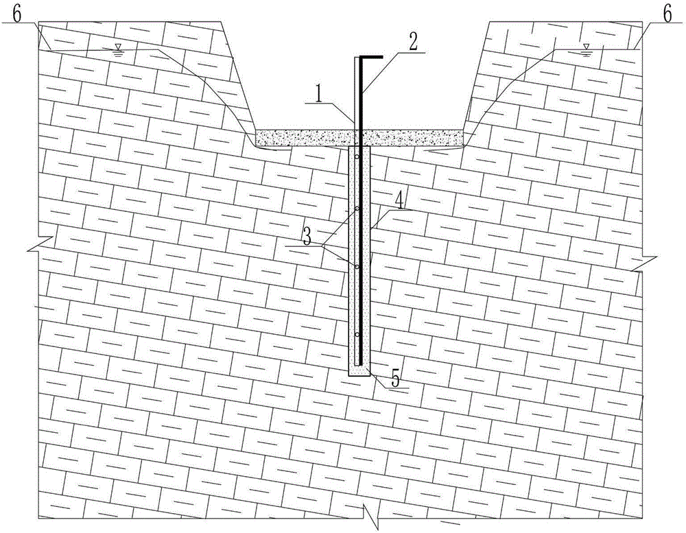
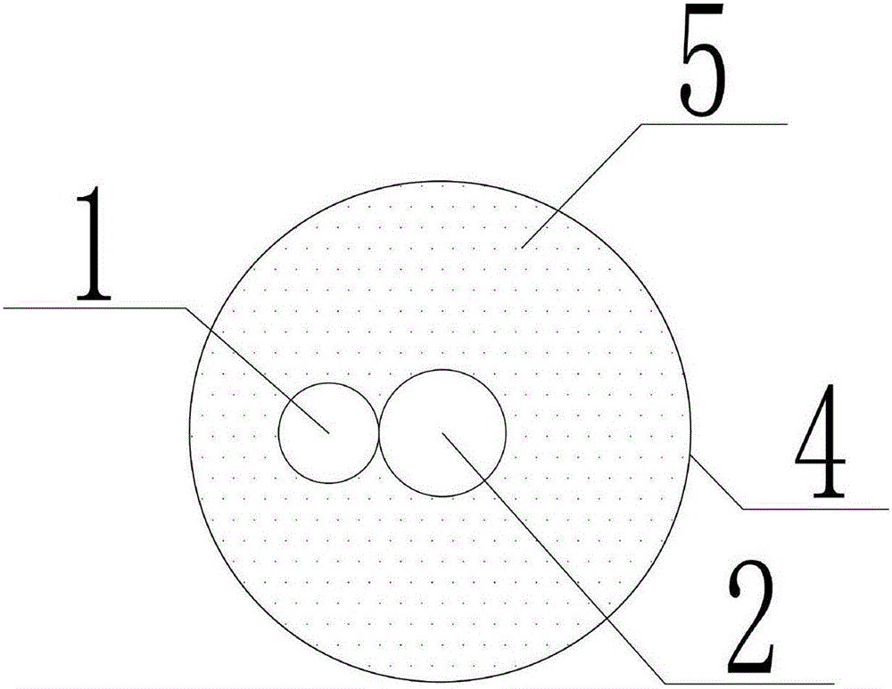
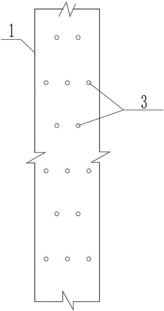
[0020] Embodiment 1: as Figure 1-Figure 3 As shown, a grouting drainage device for anti-lift anchors in carbonate rock areas, including steel pipe 1 and anti-floating anchor 2, anti-floating anchor 2 and steel pipe 1 are fixed side by side by steel wires and extend into the grouting hole 4 Inside, the steel pipe 1 extends into the grouting hole 4 and a section is provided with a sieve hole 3 .

[0021] Preferably, the steel pipe 1 has an outer diameter of 20-40 mm, and the anti-floating anchor rod 2 has a diameter of 28 mm, which can meet the pressure relief requirements.

[0022] Preferably, the above-mentioned sieve holes 3 extend all over the body of a section of steel pipe 1 extending into the grouting holes 4, and the sieve holes 3 have an aperture diameter of 8-10 mm, which can meet the pressure relief requirements and avoid the pressure relief effect caused by the grouting slurry passing through the sieve holes. question.

[0023] Preferably, the above-mentioned siev...

Embodiment 2

[0025] Embodiment 2: A kind of construction method of anti-lift bolt grouting drainage device in carbonate rock area, this method comprises the following steps:

[0026] Step 1, after the confined water level 6 in the foundation pit is pumped below the bottom of the pit, measure and stake out, locate the position of the grouting hole 4, and make a mark;

[0027] Step 2, use drilling equipment to drill the grouting hole 4 mark vertically downwards to the specified depth with a hole diameter of 130mm;

[0028] Step 3, put the 25mm steel pipe 1 tied side by side and the anti-floating anchor rod 2 with a diameter of 28mm into the grouting hole 4;

[0029] Step 4: Carry out high-pressure grouting to the grouting hole 4. After the grouting is completed, the steel pipe is not pulled out, so that it forms an anchor together with the anti-floating anchor rod to jointly resist the pull-out force.


PUM


Abstract

The invention discloses a carbonate rock area pulling-resistant anchor rod grouting and drainage device and a construction method of the carbonate rock area pulling-resistant anchor rod grouting and drainage device. The device comprises a steel pipe and an anti-floating anchor rod. The anti-floating anchor rod and the steel pipe are bound and fixed side by side and stretch into a grouting hole, and the section, stretching into the grouting hole, of the steel pipe is provided with sieve holes. The steel pipe with the sieve holes and the anti-floating anchor rod are bound, fixed and placed into the anchor rod grouting hole, and drainage and pressure relief are carried out through the sieve holes during grouting, so that grouting pressure is effectively reduced, the grouting difficulty is lowered, grouting is rapider, particularly, the secondary grouting effect is better, the problem that grouting of the anti-floating anchor rod is difficult due to the high water pressure of a carbonate rock area is effectively solved, and the carbonate rock area pulling-resistant anchor rod grouting and drainage device further has the advantages of being simple in structure, low in cost and convenient to operate.

Description

technical field [0001] The invention relates to an anti-lift bolt grouting drainage device and a construction method thereof under the condition of a pressurized water head in a carbonate rock area, and belongs to the technical field of bolt grouting. Background technique [0002] In recent years, with the large-scale development of underground space, more and more problems have arisen with the development of underground engineering, among which there are many cases where underground structures are damaged due to water buoyancy. During the construction of some projects, due to the small number of upper floors, the self-weight of the structure is often not enough to resist the buoyancy generated by groundwater, resulting in large-scale cracking and uplift of the basement floor; economic loss. Therefore, the problem of anti-floating has always been a problem that engineering designers pay attention to. [0003] For the anti-floating design of the basement floor, the common d...

Claims


Application Information

Patent Timeline
Patent Type & Authority Applications(China)
IPC IPC(8): E02D5/74E02D19/10E02D15/04E02D31/12
CPCE02D5/74E02D15/04E02D19/10E02D31/12
Inventor 沈志平张建磊袁江文孙洪朱军陈德茂吴斌
Owner ZHENGYE ENG & INVESTMENT INC
Why Eureka
Try Eureka