
Electric drive propellant feeding system liquid-propellant rocket engine
A supply system and liquid rocket technology, applied in the field of aerospace science, can solve the problems of high development cost, long development cycle, complex structure, etc., and achieve the effects of short development cycle, low investment cost and simple system design
- Summary
- Abstract
- Description
- Claims
- Application Information
AI Technical Summary
Problems solved by technology
Method used
Image

Examples
Embodiment Construction
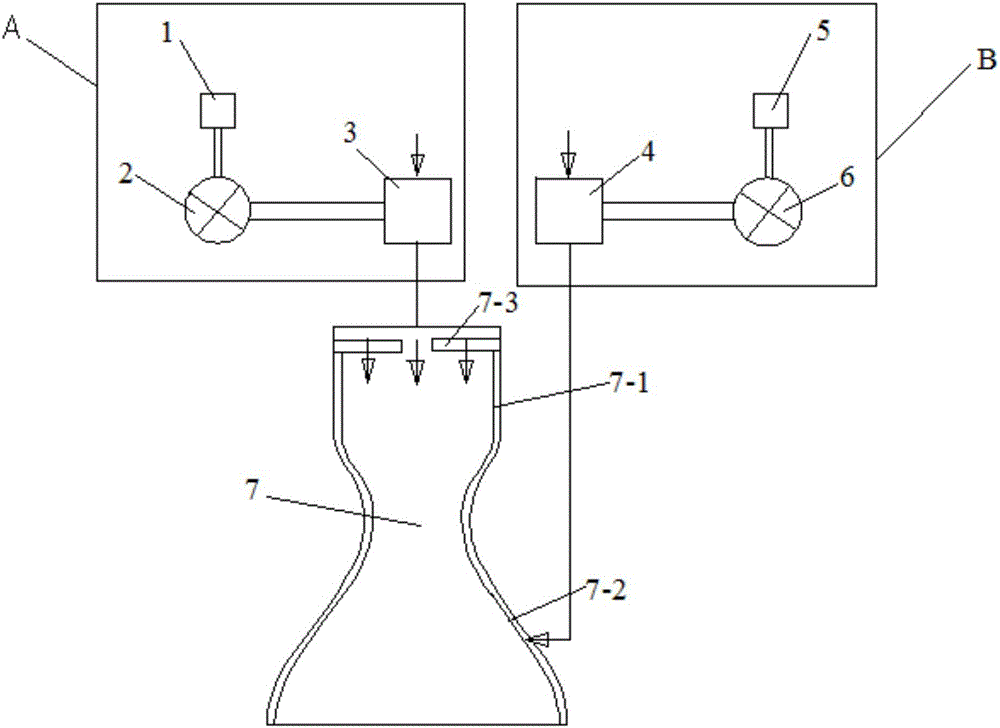
[0013] The electric drive propellant supply system liquid rocket engine of the present invention, such as figure 1 As shown, it includes an oxidant delivery system A, a fuel delivery system B, and a thrust chamber 7, and the oxidant delivery system A and the fuel delivery system B are independently communicated with the thrust chamber 7, so as to deliver corresponding oxidant and fuel into the thrust chamber 7 , and mixed and burned in the thrust chamber 7, and sprayed out from the nozzle to generate reverse thrust. The above-mentioned oxidant delivery system A includes an oxidant cell 1 , an oxidant motor 2 and an oxidant pump 3 connected in sequence, and the oxidant pump 3 is used to connect with the oxidant storage tank and the thrust chamber 7 in pipelines.
[0014] The above-mentioned fuel delivery system B includes a fuel cell 5 , a fuel motor 6 and a fuel pump 4 connected in sequence, and the fuel pump 4 is used to connect the fuel storage tank and the thrust chamber 7 ...
PUM
 Abstract
Description
Claims
Application Information