
Multichannel system sound field reconstruction method and apparatus

A sound field reconstruction and multi-channel technology, applied in the field of acoustics, can solve problems such as inability to reconstruct a three-dimensional sound field, reconstruction errors, not in the central listening point or central listening area, etc.

Active Publication Date: 2017-04-05
WUHAN UNIV
View PDF4 Cites 20 Cited by
  • Summary
  • Abstract
  • Description
  • Claims
  • Application Information

AI Technical Summary

Problems solved by technology

However, both the traditional 22.2 multi-channel system and the 22.2 streamlined system based on the Akio Ando method can only reproduce the three-dimensional listening effect of the original sound source with high quality at the central listening point or central listening area. However, in actual listening In the environment, the listener is sometimes located at the central listening point or the central listening area, and sometimes it may be necessary to change the position without being at the central listening point or the central listening area, because the listener has the ability to not be in the central listening area It is necessary and possible that the listener cannot always be located at the central listening point or central listening area of ​​the system. At this time, at the non-central listening point or non-central listening area, due to the traditional 22.2 multi-channel system and the Akio-based The theoretical limitations of the 22.2 streamlined system of the Ando method, these technologies will bring large reconstruction errors, and cannot reconstruct the three-dimensional sound field well in the non-central listening area, providing the best listening experience for the listener

Method used


Image

  • Multichannel system sound field reconstruction method and apparatus
  • Multichannel system sound field reconstruction method and apparatus
  • Multichannel system sound field reconstruction method and apparatus

Examples


Embodiment Construction

[0128] Aiming at an original multi-channel system containing any number of loudspeakers, the present invention proposes a multi-channel system reconstruction technical solution, the core technology of which is to replace the original multi-channel system with the speaker group of the reconstructed multi-channel system The loudspeaker group achieves high-fidelity reproduction of the three-dimensional sound field in the non-central area. The technical solution of the present invention will be described in detail below in conjunction with the accompanying drawings and specific embodiments.

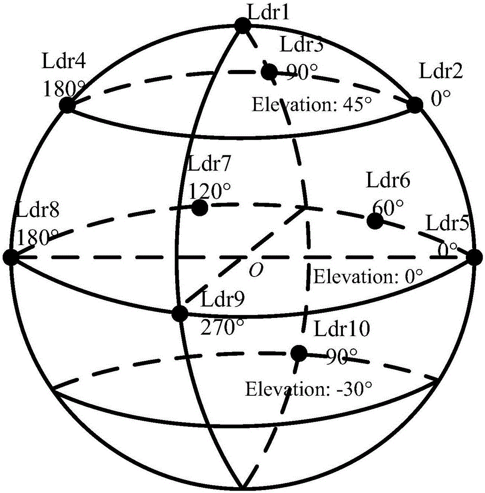
[0129] In order to implement reconstruction processing of a multi-channel system containing any number of speakers with any number of speakers, and the speakers in the original system and the reconstruction system can be placed in any position. The present invention provides a method for reconstructing a multi-channel system including m loudspeakers by using a multi-channel system including n...


PUM


Abstract

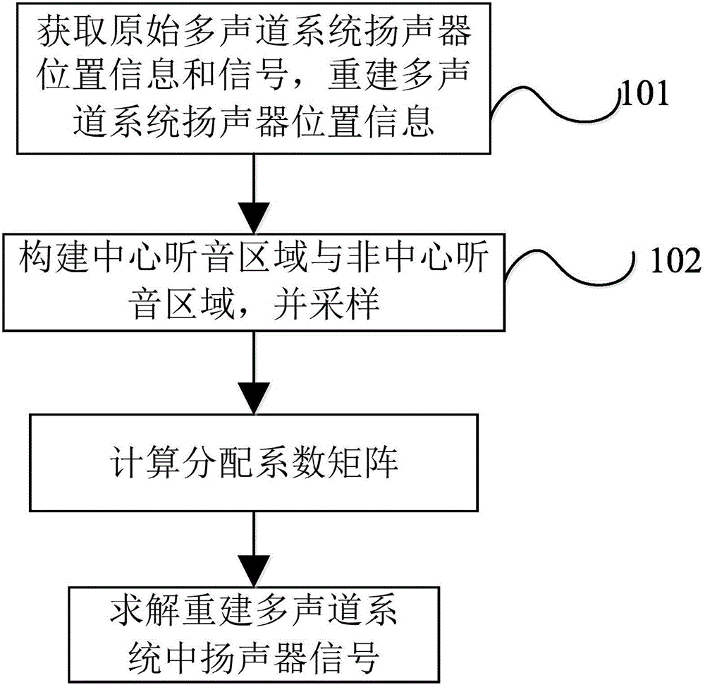
The invention provides a multichannel system sound field reconstruction method and apparatus. The method comprises steps of acquiring loudspeaker set position information in a primary multichannel system and signal information, reconstructing loudspeaker position information in the multichannel system, and listening area sampling point position information, building a central listening area and a non-central listening area, selecting sampling points in these areas, calculating distribution coefficient matrix distributed to all loudspeakers of the reconstructed multichannel system by each loudspeaker in the primary multichannel system, and calculating final distribution signals of all loudspeakers in the reconstructed multichannel system. High-quality 3D sound field can be only displayed in a central listening point or a central listening area by a traditional method, so practical demands of listening in a non-central point cannot be met for people; based on physical features of the sound field, the provided technical scheme enables a listener to acquire optimal listening feeling in any positions in reconstructed sound fields such as the central listening area or the non-central listening area.

Description

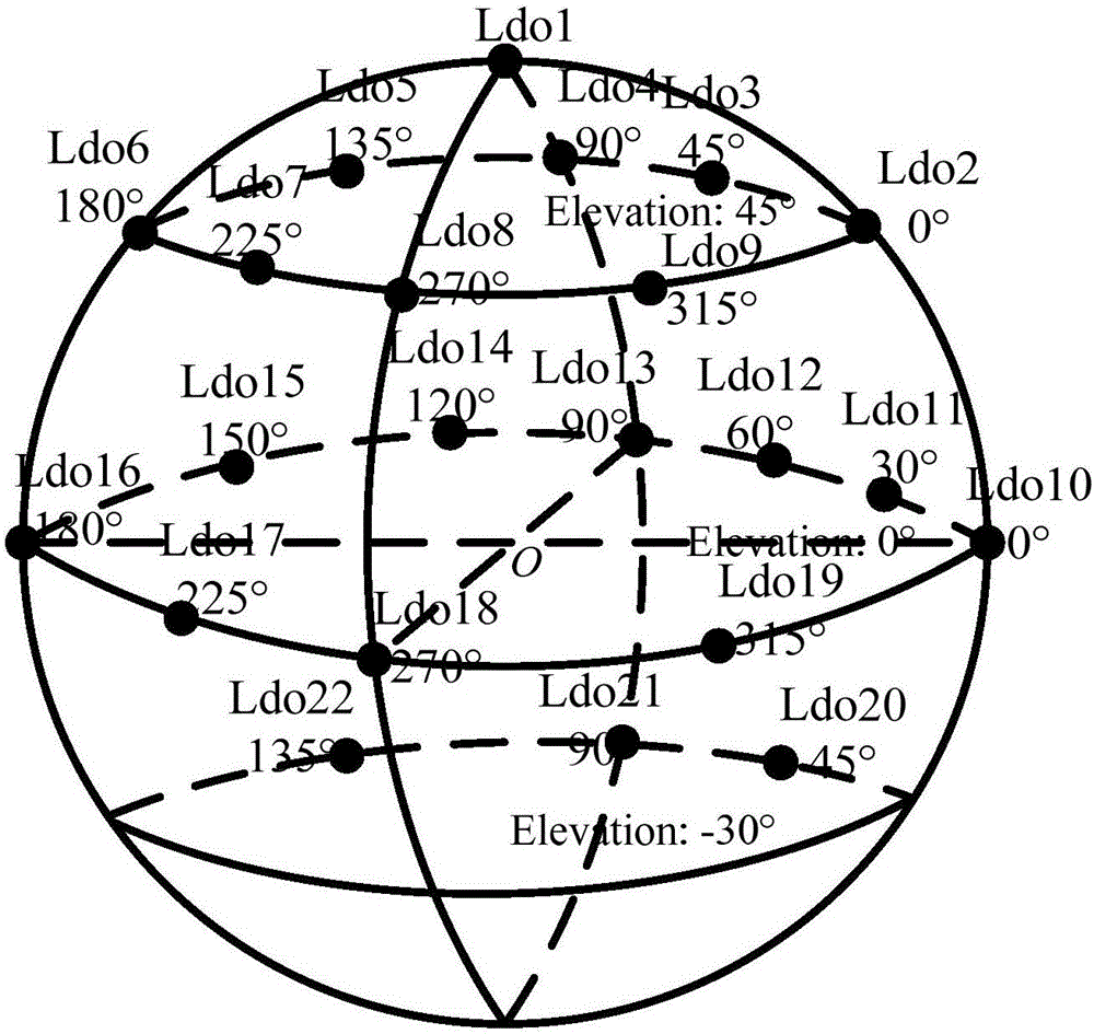
technical field [0001] The invention belongs to the field of acoustics, in particular to a multi-channel system sound field reconstruction method and device. Background technique [0002] In recent years, audio technology has made great progress. Traditional surround sound and stereo technology have gradually developed into the current three-dimensional audio technology. The effect of reconstructing the sound field has gradually expanded from zero-dimensional to three-dimensional including horizontal azimuth, elevation angle, and distance information. Among them, the vector based amplitude panning technology (vector based amplitude panning abbreviated as VBAP) is widely recognized because of its simple and convenient use. The VBAP technology is based on the method of mathematical vector synthesis, which can use three speakers to synthesize a virtual sound source. Based on VBAP technology, the Japan Broadcasting Association Laboratory proposed a 22.2 multi-channel system, whi...

Claims


Application Information

Patent Timeline
IPC IPC(8): H04S3/00H04S7/00
CPCH04S3/00H04S7/302
Inventor 胡瑞敏王松王晓晨杨乘陈玮杨玉红
Owner WUHAN UNIV
Learn More