Method and device for reducing network delay in wireless communication
A wireless communication and low-latency technology, which is applied in the field of control channels for low-latency transmission, can solve problems such as unusability, and achieve the effect of reducing load size, improving transmission efficiency or robustness
- Summary
- Abstract
- Description
- Claims
- Application Information
AI Technical Summary
Problems solved by technology
Method used
Image
Examples
Embodiment 1
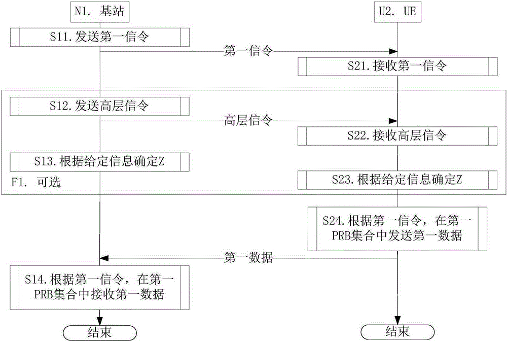
[0117] Embodiment 1 illustrates a flow chart of an embodiment including sending and receiving high-level signaling, and determining the Z step, as shown in the attached figure 1 shown. attached figure 1 In , the base station N1 is the maintenance base station of the serving cell of the UE U2, and the steps identified in the block F1 are optional steps.
[0118] For the base station N1, the first signaling is sent in step S11.
[0119] Wherein, the first signaling is a physical layer signaling, and the first signaling includes scheduling information of the first data. The first data includes N transport block groups, where N is a positive integer, and the N transport block groups are respectively transmitted in N LTE time slots. The first signaling is used to indicate that the number of bits of the first PRB set is less than or equal to Y+2, and the Y is a resource block determined according to the scheme of LTE DCI format 0 for the carrier scheduled by the first signaling ...
Embodiment 2
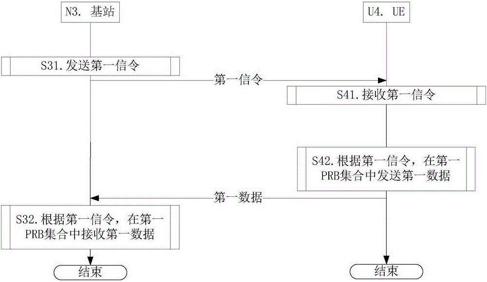
[0219] Embodiment 2 illustrates a flow chart of an embodiment that does not include sending and receiving high-level signaling, and does not include the step of determining Z, as shown in the attached figure 2 shown. attached figure 2 In , the base station N3 is the maintenance base station of the serving cell of the UE U4.
[0220] For the base station N3, the first signaling is sent in step S31.
[0221]Wherein, the first signaling is a physical layer signaling, and the first signaling includes scheduling information of the first data. The first data includes N transport block groups, where N is a positive integer, and the N transport block groups are respectively transmitted in N LTE time slots. The first signaling is used to indicate that the number of bits of the first PRB set is less than or equal to Y+2, and the Y is a resource block determined according to the scheme of LTE DCI format 0 for the carrier scheduled by the first signaling Number of bits allocated for...
Embodiment 3
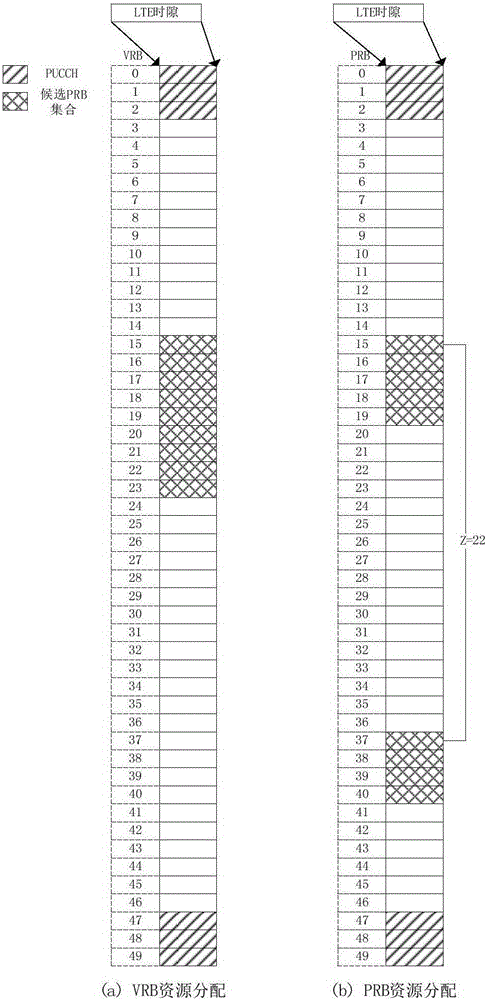
[0231] Embodiment 3 shows a schematic diagram of a resource allocation manner corresponding to a candidate PRB subset one of a candidate PRB set one according to the present invention. Assume here Then Y=11, and And 9 bits are used to indicate the position of the VRB where the first PRB set is located. Specifically, as shown in the figure, 9 bits are used to indicate the starting position of a continuous VRB RB start and its length L CRBs , the specific RB start =15,L CRBs =9, then the RIV corresponding to 9 bits can refer to the part of Section 8.1.1 of TS 36.213, here is And this embodiment corresponds to Figure (a) is a schematic diagram of VRB resource allocation indicated by RIV, and Figure (b) is a schematic diagram of PRB resource allocation based on this VRB allocation. Depend on image 3 As can be seen, the original L CRBs consecutive VRBs are divided into G=2 PRB subsets, and the first PRB subset occupies RB start to the PRB. The second PRB subset oc...
PUM
 Abstract
Description
Claims
Application Information
 - R&D
- Intellectual Property
- Life Sciences
- Materials
- Tech Scout
- Unparalleled Data Quality
- Higher Quality Content
- 60% Fewer Hallucinations
Browse by: Latest US Patents, China's latest patents, Technical Efficacy Thesaurus, Application Domain, Technology Topic, Popular Technical Reports.
© 2025 PatSnap. All rights reserved.Legal|Privacy policy|Modern Slavery Act Transparency Statement|Sitemap|About US| Contact US: help@patsnap.com


