
High-steady-state, high-effect, and large-volume fermenting tank

A high-efficiency, large-capacity technology, applied in bioreactor/fermenter combination, specific-purpose bioreactor/fermenter, biochemical equipment, etc., can solve the problem of tank weld cracking, time-consuming and laborious, and low production efficiency and other problems, to achieve energy-saving, high-efficiency production, good dissolved oxygen effect, and no replacement effect

Active Publication Date: 2017-04-19
ZIBO SANTIAN CHEM EQUIP CO LTD
View PDF6 Cites 4 Cited by
  • Summary
  • Abstract
  • Description
  • Claims
  • Application Information

AI Technical Summary

Problems solved by technology

with a tank volume of 150-300m 3 Compared with glutamic acid fermenter, 780m 3 During the production and operation of the large tank, it was found that there were generally problems such as low production efficiency, high energy consumption, and substandard fermentation parameters; in addition, the equipment was not running stably, and the swing of the tank body reached 50 mm. Second, the operation reliability is poor. After each fermentation batch, the operator must enter the tank for inspection. The maintenance frequency is high, time-consuming and labor-intensive, and the production arrangement is often delayed. By analyzing the reasons, it is In terms of safety problems caused by unstable equipment operation, it is all related to the transmission seal of the tank, the concentricity of the stirring shaft, and the unreasonable setting of the stirring support frame.

Method used


Image

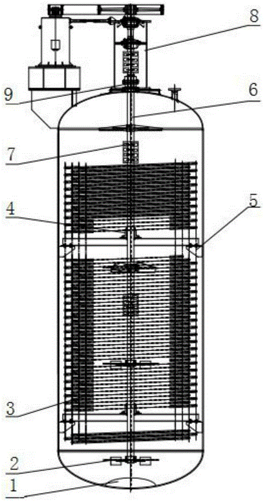
  • High-steady-state, high-effect, and large-volume fermenting tank
  • High-steady-state, high-effect, and large-volume fermenting tank
  • High-steady-state, high-effect, and large-volume fermenting tank

Examples


Embodiment Construction

[0033] The present invention will be further described below in conjunction with the accompanying drawings and embodiments.

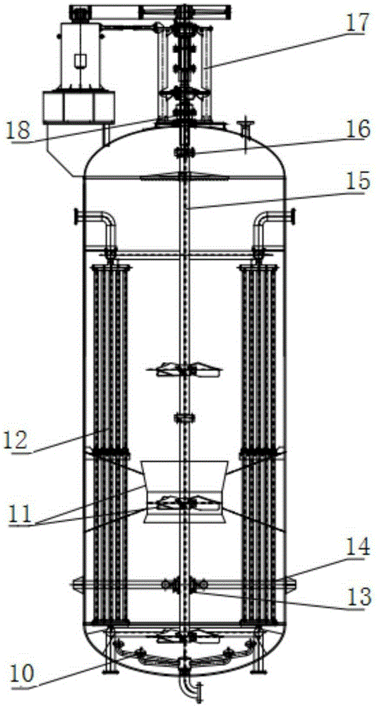
[0034] like figure 2As shown, the high-steady-state, high-efficiency and large-volume fermentation tank includes two parts outside the tank and inside the tank. Except for the tank body, the motor base, and the pulley outside the tank, the frame of the stirring transmission device adopts a four-column frame 17. The overall stability is enhanced, and the space in the column becomes larger, which is convenient for the installation and maintenance of the coupling and mechanical seal. The original cylindrical frame is very inconvenient for the installation and maintenance of couplings and mechanical seals due to the small internal space;

[0035] The mechanical seal at the top of the tank at the center of the upper head adopts the 204J static mechanical seal 18 in the application number 201520013895.2. During the operation, due to the good floating of the...


PUM

PropertyMeasurementUnit
poweraaaaaaaaaa

Abstract

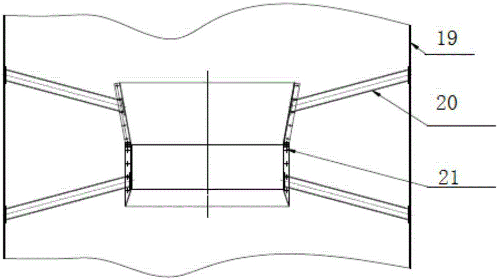
The invention discloses a high-steady-state, high-effect, and large-volume fermenting tank. The fermenting tank comprises a tank body, wherein a hollow stirring shaft is perpendicularly arranged in the center of the interior of the tank body; a plurality of stirrers for performing axial flowing of a fermenting liquid in the tank body are uniformly distributed on the hollow stirring shaft; the lower part of the hollow stirring shaft is connected with a middle bearing bracket through a middle bearing; multiple groups of vertical type column pipe coolers are distributed, in the axial direction of the tank body, in the interior of the tank body; a multi-bubble-cap air distributing apparatus is arranged at the bottom of the tank body; the multi-bubble-cap air distributing apparatus comprises a main air pipe; and the main air pipe is connected to the exterior of the tank body. By virtue of the mechanical units, comprising an external transmission rack, a tank top mechanical sealing part, the stirring shafts, a coupler, the middle bearing bracket and a wear-resisting bearing bush, for constituting the fermenting tank structure, the operational stability of the fermenting tank is greatly improved; full guarantee is provided for energy-saving, consumption-reducing and high-efficient production; and obvious economic benefits and a demonstration effect are achieved.

Description

technical field [0001] The invention relates to a fermentation tank for industrial fermentation of amino acids, in particular to a 780m glutamic acid fermentation enterprise 3 The series of innovative technological transformations of large fermentation tanks belong to the technical field of biological fermentation engineering. Background technique [0002] The sodium salt of glutamic acid neutralized by alkali is monosodium glutamate. Demand, the production scale of monosodium glutamate production enterprises is constantly expanding. There are several enterprises in my country with an annual output of hundreds of thousands of tons to one million tons, and the output has accounted for about 85% of the world's total output. The increase in the production capacity of existing glutamic acid fermentation enterprises is mainly achieved by increasing the volume of the fermenter, so as to achieve economies of scale. Therefore, the volume of the glutamic acid fermenter has increased ...

Claims


Application Information

Patent Timeline
Patent Type & Authority Applications(China)
IPC IPC(8): C12M1/04C12M1/02C12M1/00
CPCC12M27/08C12M27/24C12M29/08C12M37/04C12M41/24
Inventor 田克勤王千祥
Owner ZIBO SANTIAN CHEM EQUIP CO LTD
Learn More