Lifting hydro-pneumatic suspension hydraulic system

A technology of hydraulic system and oil and gas suspension, applied in the field of hydraulic system, can solve the problem that the hydraulic system of the liftable oil and gas suspension cannot fully realize automatic control, reduce the reliability of the hydraulic system of the liftable oil and gas suspension, and reduce the hydraulic pressure of the liftable oil and gas suspension. System efficiency and other issues, to achieve excellent reliability and comprehensive performance, good anti-pollution, good sealing effect

Active Publication Date: 2017-04-19
SPECIAL VEHICLE TECH CENT OF HUBEI AEROSPACE TECH RES INST
View PDF6 Cites 9 Cited by
  • Summary
  • Abstract
  • Description
  • Claims
  • Application Information

AI Technical Summary

Problems solved by technology

Although the manual ball valve has good pollution resistance and high reliability, it needs manual operation to control the on-off of the oil circuit, which causes the hydraulic system of the liftable oil-air suspension to not fully realize automatic control, and reduces the working efficiency of the hydraulic system of the liftable oil-air suspension.
Although the cartridge valve can realize automatic operation to control the on-off of the oil circuit, because it uses the conical surface between the spool and the valve sleeve as the sealing surface to realize the on-off of the oil circuit, the anti-pollution property is poor, and the cleanliness of the oil in the hydraulic system is poor. The requirements are high. If the oil in the hydraulic system contains more impurities, after a certain period of work, the impurities in the oil will increase the wear of the cone surface, causing the sealing performance of the cartridge valve to decline, and the cartridge valve will appear Internal leakage, eventually causing the failure of the hydraulic system of the liftable oil-pneumatic suspension, reducing the reliability of the hydraulic system of the liftable oil-pneumatic suspension

Method used


Image

  • Lifting hydro-pneumatic suspension hydraulic system
  • Lifting hydro-pneumatic suspension hydraulic system
  • Lifting hydro-pneumatic suspension hydraulic system

Examples


Embodiment 1

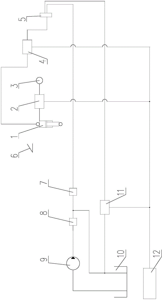
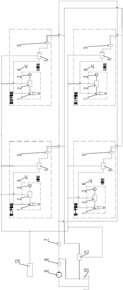
[0029] Such as figure 2 As shown, the present invention can lift the oil-pneumatic suspension hydraulic system, wherein the oil-pneumatic spring 1, the rigid cut-off valve 2, the accumulator 3, the angle sensor 6, the group oil return cut-off valve 4 and the electromagnetic reversing valve 5 form four balanced Group, the four balance groups are the first balance group, the second balance group, the third balance group and the fourth balance group, each balance group includes oil and gas spring 1, rigid stop valve 2, accumulator 3, angle sensor 6. Group oil return cut-off valve 4 and electromagnetic reversing valve 5, oil and gas spring 1, rigid stop valve 2, accumulator 3, angle sensor 6, group oil return stop valve 4 and electromagnetic reversing valve in each balance group 5 are all set to one.

[0030] This embodiment is applied to a two-axle super-heavy off-road vehicle, such as figure 2 As shown, the hydraulic system of the liftable oil-pneumatic suspension is divided...

Embodiment 2

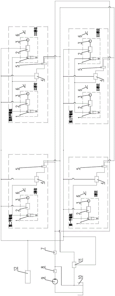
[0034] Such as image 3 As shown, the present invention can lift the oil-pneumatic suspension hydraulic system, wherein the oil-pneumatic spring 1, the rigid cut-off valve 2, the accumulator 3, the angle sensor 6, the group oil return cut-off valve 4 and the electromagnetic reversing valve 5 form four balanced Group, the four balance groups are the first balance group, the second balance group, the third balance group and the fourth balance group, each balance group includes oil and gas spring 1, rigid stop valve 2, accumulator 3, angle sensor 6. Group oil return cut-off valve 4 and electromagnetic reversing valve 5, oil-gas spring 1, rigid stop valve 2, accumulator 3, angle sensor 6, group oil return cut-off valve in the first balance group and the second balance group The valve 4 and the electromagnetic reversing valve 5 are all set to one, and the grouping oil return cut-off valve 4 and the electromagnetic reversing valve 5 in the third balance group and the fourth balance ...

Embodiment 3

[0039] Such as Figure 4 As shown, the present invention can lift the oil-pneumatic suspension hydraulic system, wherein the oil-pneumatic spring 1, the rigid cut-off valve 2, the accumulator 3, the angle sensor 6, the group oil return cut-off valve 4 and the electromagnetic reversing valve 5 form four balanced Group, the four balance groups are the first balance group, the second balance group, the third balance group and the fourth balance group, each balance group includes oil and gas spring 1, rigid stop valve 2, accumulator 3, angle sensor 6. Group oil return cut-off valve 4 and electromagnetic reversing valve 5. Set one group oil return stop valve 4 and electromagnetic reversing valve 5 in each balance group. Oil-gas spring 1 and rigid cut-off valve in each balance group There are two valves 2, accumulators 3 and angle sensors 6.

[0040] This embodiment is applied to a four-axle super-heavy off-road vehicle, such as Figure 4 As shown, the hydraulic system of the lift...


PUM


Abstract

The invention discloses a lifting hydro-pneumatic suspension hydraulic system and relates to a hydraulic system applied to an automobile hydro-pneumatic suspension. According to the lifting hydro-pneumatic suspension hydraulic system, the automation level requirements of the lifting hydro-pneumatic suspension hydraulic system are met, and meanwhile the reliability is improved. The lifting hydro-pneumatic suspension hydraulic system comprises an oil tank (10), an oil supply pump (9), a safety valve (8), a one-way valve (7), an electromagnetic reversing valve (5), a grouping oil returning stopping valve (4), a rigidity stopping valve (2), an oil gas spring (1), an energy accumulator (3), a gas storage cylinder (12), an angle transducer (6), a pneumatic pipeline and a hydraulic pipeline. The oil conveying end of the electromagnetic reversing valve is connected with one oil end of the grouping oil returning stopping valve, and the other oil end of the grouping oil returning stopping valve is connected with the hydraulic oil opening of the oil gas spring. The rigidity stopping valve is arranged between the oil gas spring and the energy accumulator communicating with the oil gas spring. The grouping oil returning stopping valve and the rigidity stopping valve both are pneumatic ball valves.

Description

technical field [0001] The invention relates to the fields of automobiles and engineering machinery, in particular to a hydraulic system suitable for vehicle oil-pneumatic suspension. Background technique [0002] Generally, the hydraulic valves used to control the on-off of the oil circuit in the hydraulic system of the liftable oil-air suspension are mainly manual ball valves or cartridge valves. Although the manual ball valve has good pollution resistance and high reliability, it needs manual operation to control the on-off of the oil circuit, which causes the hydraulic system of the liftable oil-pneumatic suspension to not fully realize automatic control, and reduces the working efficiency of the hydraulic system of the liftable oil-pneumatic suspension. Although the cartridge valve can realize automatic operation to control the on-off of the oil circuit, because it uses the conical surface between the spool and the valve sleeve as the sealing surface to realize the on-o...

Claims


Application Information

Patent Timeline
Patent Type & Authority Applications(China)
IPC IPC(8): F16F15/027F15B1/02F15B13/02
CPCF15B1/02F15B13/02F16F15/027F16F2222/12
Inventor 毛楚男王萍冯炜孔卫凯张熙隆
Owner SPECIAL VEHICLE TECH CENT OF HUBEI AEROSPACE TECH RES INST
Why Eureka
Try Eureka