Determination method of aero-engine installation center surface

A technology of aero-engine, determination method, applied in the direction of measuring device, using optical device, instrument, etc.

Active Publication Date: 2017-04-19
CHENGDU ENGINE GROUP
View PDF5 Cites 0 Cited by
  • Summary
  • Abstract
  • Description
  • Claims
  • Application Information

AI Technical Summary

Problems solved by technology

In some cases, the compound deviation may exceed the range allowed by the technical requirements of the aircraft installation

Method used


Image

  • Determination method of aero-engine installation center surface
  • Determination method of aero-engine installation center surface
  • Determination method of aero-engine installation center surface

Examples


Embodiment

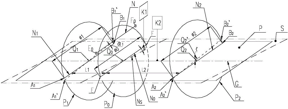
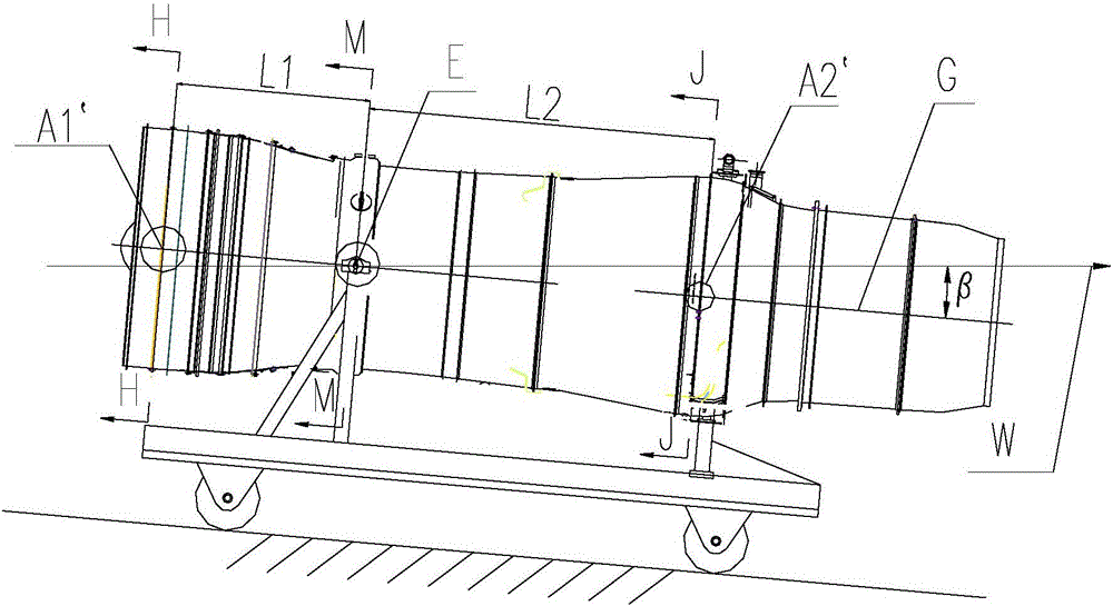
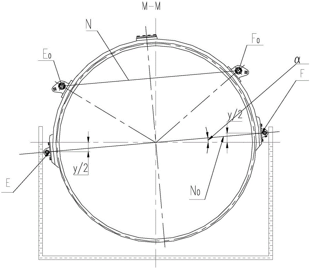
[0054] The engine of this embodiment is a turbofan engine with dual channels, and the outer circle P of the measuring point before the engine is 1 It is a single-channel casing, and the outer circle of the rear measurement point P 2 It is a double-ducted receiver, and its center Q 2 May deviate from center line G, assuming deviation ( figure 1 , Figure 5 shown along the vertical direction). According to the installation technical requirements of an aircraft, the following measuring instruments and equipment were selected to calibrate the measuring points of the center plane of an aero-engine.

[0055] Measuring instruments and equipment used:

[0056] 1) U-shaped tube (material: transparent PVC transparent plastic tube, tube size: outer diameter 4mm, tube wall thickness 1mm, length 3m), filled with tap water;

[0057] 2) EK-155AP laser line projector;

[0058] 3) The computer prints a transparent tape with a ratio of 1:1 (attached to the U-shaped tube to measure the...


PUM


Abstract

The invention discloses a determination method of an aero-engine installation center surface. The method is characterized by using an equal water level principle and adopting a transparent PVC transparent plastic U-shaped pipe, a horizontal laser ray instrument and a length measuring instrument to calibrate aero-engine measuring points, wherein a deviation of 4 front and rear measuring points and an installation center surface P is less than or equal to 1mm; and through the four measuring points, identifying the aero-engine installation center surface. The method is suitable for aero-engine delivery inspection, airplane assembling engine review inspection and loading inspection under an aero-engine outfield usage condition and a good practical engineering value is possessed.

Description

technical field [0001] The invention relates to the technology of installing an aero-engine on an aircraft, in particular to a method for determining an engine installation center plane as an installation reference in the aero-engine installation. Background technique [0002] The aero-engine is installed on the aircraft, and there are strict design requirements for the installation angle between the engine installation center plane (abbreviated as the center plane) and the assembly datum on the aircraft, so as to ensure the air flight design requirements of the aircraft. The installation center plane of aero-engine is identified by measuring points on the aero-engine casing in engineering practice. Existing part aero-engine is in manufacturing production process, and its measuring point has been processed in its components (casing at the outer circle place of installation joint measuring point, front measuring point and rear measuring point) process. In order to show the d...

Claims


Application Information

Patent Timeline
Patent Type & Authority Applications(China)
IPC IPC(8): G01B11/26
CPCG01B11/26
Inventor 罗华川段红春闫金友冯祥金许韬王洪惠刘杨彭武龙
Owner CHENGDU ENGINE GROUP
Why Eureka
Try Eureka