
Tracer-gas-volume-fraction-based integral measurement and calculation method for air leakage of working face behind support

A technology of tracer gas and volume fraction, applied in the direction of liquid tightness measurement using liquid/vacuum degree, measuring device, and detecting the appearance of fluid at the leak point, etc., which can solve the problem of rough results, less application, and heavy testing workload and other problems, to achieve the effect of high accuracy, easy operation and simple method

Inactive Publication Date: 2017-04-19
ANHUI UNIV OF SCI & TECH
View PDF5 Cites 12 Cited by
  • Summary
  • Abstract
  • Description
  • Claims
  • Application Information

AI Technical Summary

Problems solved by technology

The first method is affected by the accuracy of the air flow test and the inability of each measurement section to be carried out at the same time, the result is relatively rough, and the test workload is large, and the application is less
The second test method assumes that the air leakage source is only a point on the side of the air inlet roadway in the goaf, and fails to consider the overall characteristics of the air leakage along the face length direction, which is inconsistent with the actual situation; and because the release point is located on the working face, it will cause tracer gas to leak into After the goaf, it leaks at the test point, so that the tracer gas volume fraction at each test point is not equal to high, resulting in inaccurate test results

Method used


Image

  • Tracer-gas-volume-fraction-based integral measurement and calculation method for air leakage of working face behind support

Examples


Embodiment Construction

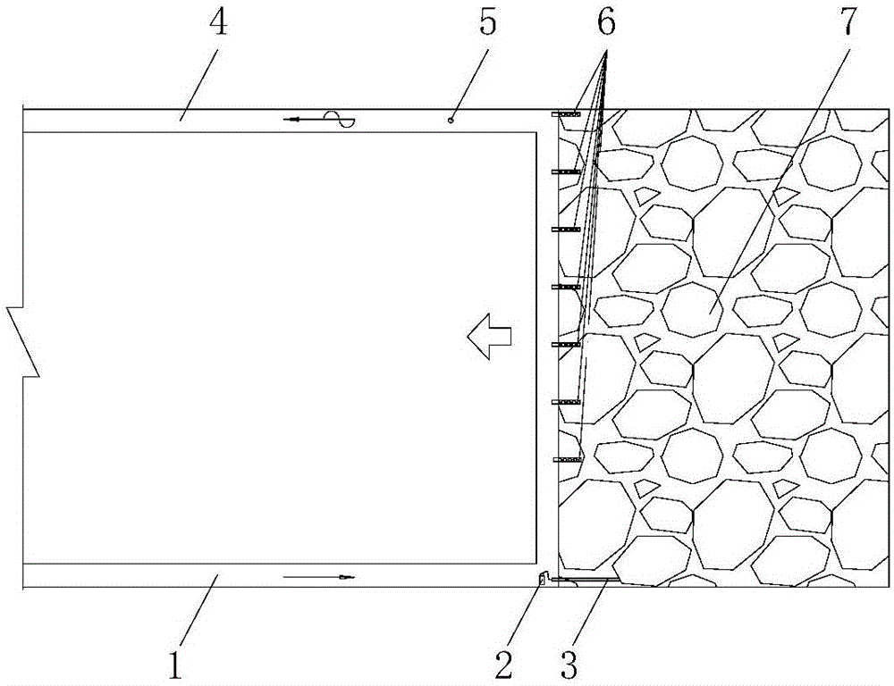
[0008] Such as figure 1 As shown, a tracer gas volume fraction integration method for calculating the air leakage behind the working face frame is carried out as follows:

[0009] Arrange tracer gas release steel cylinders on the air inlet side of the lower corner of the working face, and release the tracer gas in a constant amount to a certain depth in the goaf near the lower corner of the working face by using pressure reducing valves, flow control devices and release pipes to avoid Effect of wind flow pressure on tracer gas.

[0010] At intervals of a certain number of supports along the length of the working face, the gas measuring tube is used to extend into the support from the gap between the supports, extract the gas in the goaf, inject it into the gas sampling bag, bring it to the ground, and use the gas chromatograph to analyze the gas. trace gas volume fraction.

[0011] Take the surface length direction as the abscissa and the tracer gas volume fraction as the or...


PUM


Abstract

The invention discloses a tracer-gas-volume-fraction-based integral measurement and calculation method for an air leakage of a working face behind a support. At a lower corner angle of a working face, tracer gas is released to a place with the certain depth in a goaf region near the lower corner angle of the working face at a constant amount; gas is extracted from gaps between supports by using gas measuring pipes at certain intervals along the working face length direction; a tracer gas volume fraction at a measuring point is analyzed; a tracer gas volume fraction distribution curve after supports is drawn, wherein a horizontal coordinate region included under the curve is a goaf facing working face tunnel air-leak region. With the integral method, the area encircled by the tracer gas volume fraction curve is solved and a tracer gas volume fraction of goaf air-leak attenuation is obtained; the attenuation tracer gas volume is divided by the tracer gas volume fraction to obtain a total air leak value of leaking in the goaf of the U-shaped ventilating working face. A ratio value of all segments of tracer gas volume fractions to volume fractions after integration is multiplied by the total air leak value of the goaf to obtain all air leak values of the working face.

Description

technical field [0001] The invention relates to the technical field of air leakage detection in coal mines, and is suitable for a method for testing air leakage in a goaf behind a support in a coal mining face. Background technique [0002] During the advancing process of the coal mining face with the U-shaped ventilation method in the coal mine, it is inevitable that the air flow on the air inlet side of the working face will leak into the goaf behind the support, and then enter the working face at the return air side of the working face. This kind of air leakage is not only not conducive to the prevention and control of spontaneous combustion of residual coal in the goaf, but also not conducive to the gas prevention, ventilation and dust removal and cooling of the coal mining face. In order to reduce the air leakage in the goaf, the coal mine adopts the method of stacking and filling the upper and lower corners of the working face and hanging the wind curtain on the air in...

Claims


Application Information

Patent Timeline
IPC IPC(8): G01M3/20G01N30/02
CPCG01M3/20G01N30/02
Inventor 秦汝祥吴灿春尹鹏飞张晋京杨应迪唐明云周亮邱进伟
Owner ANHUI UNIV OF SCI & TECH
Learn More