A pneumatic wire stripping device

A technology of wire stripping device and wire crimping device, which is applied in the direction of electrical components, circuit/collector components, connections, etc., can solve the problems of not being able to adapt to large-scale production, low efficiency of manual operation, and low efficiency of wire stripping, and achieve Good positioning effect, convenient for later maintenance and replacement, good drawing effect

Active Publication Date: 2018-11-20
DONGGUAN UNIV OF TECH
View PDF6 Cites 0 Cited by
  • Summary
  • Abstract
  • Description
  • Claims
  • Application Information

AI Technical Summary

Problems solved by technology

[0003] When the cable is connected, it is necessary to combine the metal inside. Therefore, the first step is to peel off the cable at the connector end, peel off the plastic outer skin, and then splice the inner metal part. Some wire stripping is mostly manual operation, and the plastic at the end of the cable is stripped off manually through the wire stripper. However, the manual operation is inefficient and cannot adapt to large-scale production. Therefore, some wire stripping machines have appeared, but The wire needs to realize two-step action, that is, the action of clamping and pulling. Most of the existing wire stripping machines are relatively complicated. The complex mechanical structure is used to realize the clamping and pulling, which consumes a lot of energy and the stripping efficiency is not high.

Method used


Image

  • A pneumatic wire stripping device
  • A pneumatic wire stripping device
  • A pneumatic wire stripping device

Examples


Embodiment Construction

[0034] In order to enable those skilled in the art to better understand the technical solutions of the present invention, the present invention will be described in detail below with reference to the accompanying drawings. The description in this section is only exemplary and explanatory, and should not have any limiting effect on the protection scope of the present invention. .

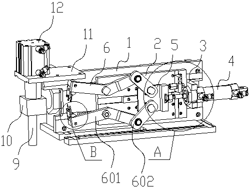
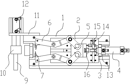
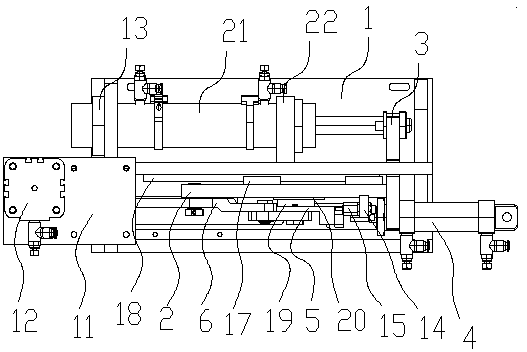
[0035] Such as Figure 1-Figure 7 As shown, the specific structure of the present invention is: a pneumatic wire stripping device, which includes a frame 1 and a wire crimping device 10 arranged on the left side pillar 9 of the frame 1, and a movable plate is arranged on the frame 1 2. The right side of the movable plate 2 is fixedly connected with a linkage block 3, the front and rear ends of the linkage block 3 are respectively installed with a thread clamping cylinder 4 and a left and right movable device, the cylinder head of the thread clamping cylinder 4 A wire clamping push plate 5 is connected,...


PUM


Abstract

The present invention relates to the field of cable processing, in particular to a pneumatic wire stripping device; The right side of the plate is fixedly connected with a linkage block, and the front and rear ends of the linkage block are respectively equipped with clamping cylinders and left and right movable devices. The cylinder head of the clamping cylinder is connected with a clamping push plate. There are two clamping rods that cooperate with each other on the wire push plate. The left end of the clamping rod is provided with a stripping card that cooperates with the cable. The position of the stripping card is the same as that of the crimping device. Coordination; the purpose of this invention is to provide a pneumatic wire stripping device, the wire clamping part is set on the left and right movable devices, and the wire clamping is realized through the cooperation of the cylinder and the connecting rod, which greatly simplifies the structure of the wire stripping device and greatly improves Improve the efficiency of stripping and save the cost of stripping.

Description

Technical field [0001] The invention relates to the field of cable processing, in particular to a pneumatic wire stripping device. Background technique [0002] With the advent of the electrification era, people’s demand for cables is increasing. Almost everyone will use cables; in the process of cable applications, it is often necessary to simply and splice cables, that is Wiring is often required. [0003] When the cable is connected, the metal inside needs to be combined. Therefore, the first step is to strip the cable at the connector end, peel off the plastic outer skin, and expose the metal part inside, and then splice it. Some wire stripping is mostly performed manually, and the plastic at the end of the cable is stripped manually using wire strippers. However, the manual operation efficiency is low and cannot be adapted to large-scale production. Therefore, some wire stripping machines have appeared. The wire needs to realize two-step action, namely the action of wire cla...

Claims


Application Information

Patent Timeline
Patent Type & Authority Patents(China)
IPC IPC(8): H01R43/28
CPCH01R43/28
Inventor 邓君
Owner DONGGUAN UNIV OF TECH
Why Eureka
Try Eureka