
Digitalized three-phase system power factor correction apparatus and correction method

A power factor correction and power factor technology, applied in the direction of reactive power adjustment/elimination/compensation, reactive power compensation, etc., can solve the problem that the PFC correction system is inconvenient for coordinated control, the control circuit has many components, and is easily disturbed by noise. and other problems, to achieve the effect of overcoming product performance dispersion, small temperature drift and good stability

Inactive Publication Date: 2017-04-19
中国船舶重工集团公司第七二三研究所
View PDF4 Cites 4 Cited by
  • Summary
  • Abstract
  • Description
  • Claims
  • Application Information

AI Technical Summary

Problems solved by technology

[0004] Among many circuit topologies and control methods, the fully decoupled three-phase six-switch high-frequency PWM rectifier has good performance in both circuit topology and control effect, and is currently recognized by the academic community as the most promising large-capacity Three-phase DC power supply system solution, but due to the complexity of the control algorithm, it has not yet entered the commercialization stage in a complete sense
[0005] The analog control method of PFC is simple and direct, but there are many components in the control circuit, the circuit adaptability is poor, it is easy to be disturbed by noise, and the debugging is laborious
If an analog PFC correction chip is used to implement active power factor correction, the PFC correction system is not convenient for coordinated control with other control systems

Method used


Image

  • Digitalized three-phase system power factor correction apparatus and correction method
  • Digitalized three-phase system power factor correction apparatus and correction method
  • Digitalized three-phase system power factor correction apparatus and correction method

Examples


Embodiment Construction

[0020] It is easy to understand that, according to the technical solution of the present invention, those skilled in the art can imagine various implementations of the digital three-phase system power factor correction device and method of the present invention without changing the essence of the present invention. Therefore, the following specific embodiments and drawings are only exemplary descriptions of the technical solution of the present invention, and should not be regarded as the entirety of the present invention or as a limitation or limitation on the technical solution of the present invention.

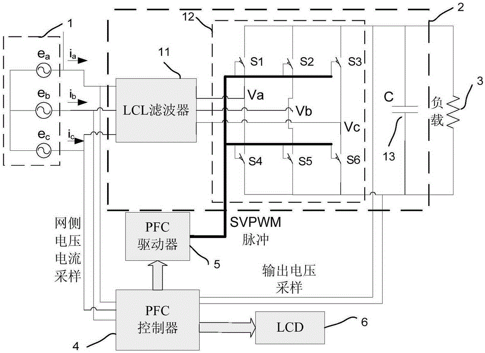
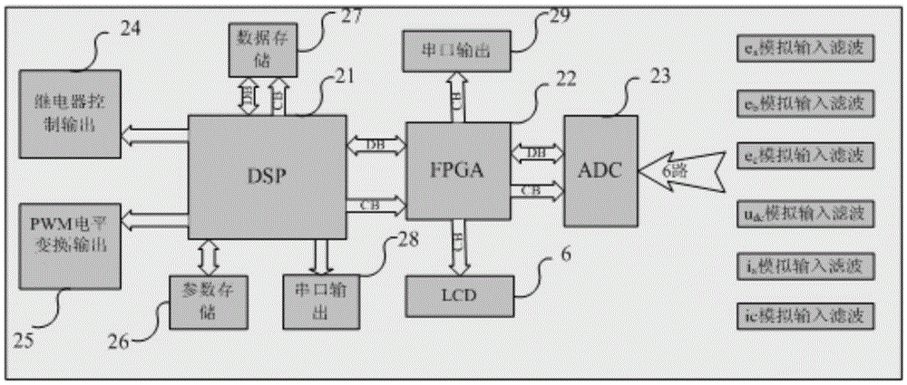
[0021] The structural block diagram of the three-phase system power factor correction device in this embodiment is as follows figure 1 As shown, the three-phase system power factor correction device includes a power factor correction main circuit 2 , a PFC controller 4 (power factor correction digital controller), a PFC driver 5 and an LCD display 6 . The power factor corre...


PUM


Abstract

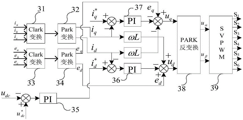
The invention provides a digitalized three-phase system power factor correction apparatus and a correction method. The digitalized three-phase system power factor correction apparatus comprises a power factor correction main circuit, a PFC controller, a PFC driver and an LCD display screen, wherein the power factor correction main circuit comprises an LCL three-phase filter, a three-phase six-switch full-bridge rectification circuit and a DC filtering capacitor, and the PFC controller comprises a simulation voltage and current signal acquisition module, an algorithm processing module and a digital modulation pulse output module. The algorithm processing module employs a digitalized mode to realize full-decoupling control, the digital modulation pulse output module generates spatial vector modulation pulses according to the output result of the algorithm processing module by using a digitalized pulse-width modulation method to complete driving of three-phase six switches. The power factor is high, the input current harmonic wave distortion is small, the efficiency is high, bidirectional transmission of power can be realized, and the digitalized three-phase system power factor correction apparatus is suitable for large-power occasions.

Description

technical field [0001] The invention relates to the field of three-phase system power factor correction, in particular to a digital three-phase system power factor correction device and method. Background technique [0002] In modern industry, large-scale DC motor power supply, arc welding power supply, aviation battery charging power supply, etc., have an increasing demand for high-power power factor correction (PFC), so high-power three-phase PFC has become a research hotspot in recent years. The basic topology of three-phase PFC includes three-phase single-switch PFC topology, three-phase two-switch PFC topology, three-phase three-switch PFC topology, three-phase six-switch PFC topology and three-phase multi-level rectification topology. Among them, the three-phase six-switch boost PFC topology has become the first choice for large-capacity three-phase PFC topology due to its characteristics of small harmonic distortion of input current, high power factor, high efficiency...

Claims


Application Information

Patent Timeline
Patent Type & Authority Applications(China)
IPC IPC(8): H02J3/18
CPCY02E40/30
Inventor 刘刚孙前刚栾铸征陆小凯张彦潘李云
Owner 中国船舶重工集团公司第七二三研究所
Learn More