
Radio frequency matching system and method of realizing radio frequency matching automation

A radio frequency matching and radio frequency technology, applied in the baseband system, transmission system, digital transmission system, etc., can solve problems such as low yield rate and large engineering time consumption, reduce workload, improve accuracy, and facilitate mass production of matching chips and the effect of assembling the PCB

Inactive Publication Date: 2017-04-19
YULONG COMPUTER TELECOMM SCI (SHENZHEN) CO LTD
View PDF5 Cites 8 Cited by
  • Summary
  • Abstract
  • Description
  • Claims
  • Application Information

AI Technical Summary

Problems solved by technology

This process consumes a lot of engineering time, and the yield of manually soldering such tiny devices is very low

Method used

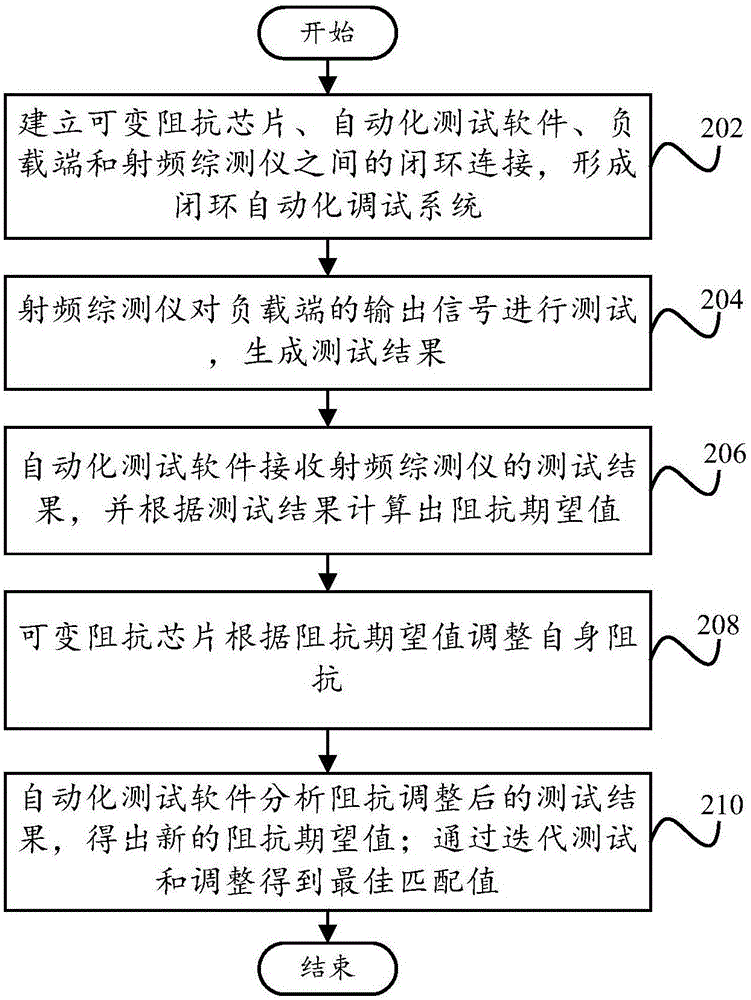
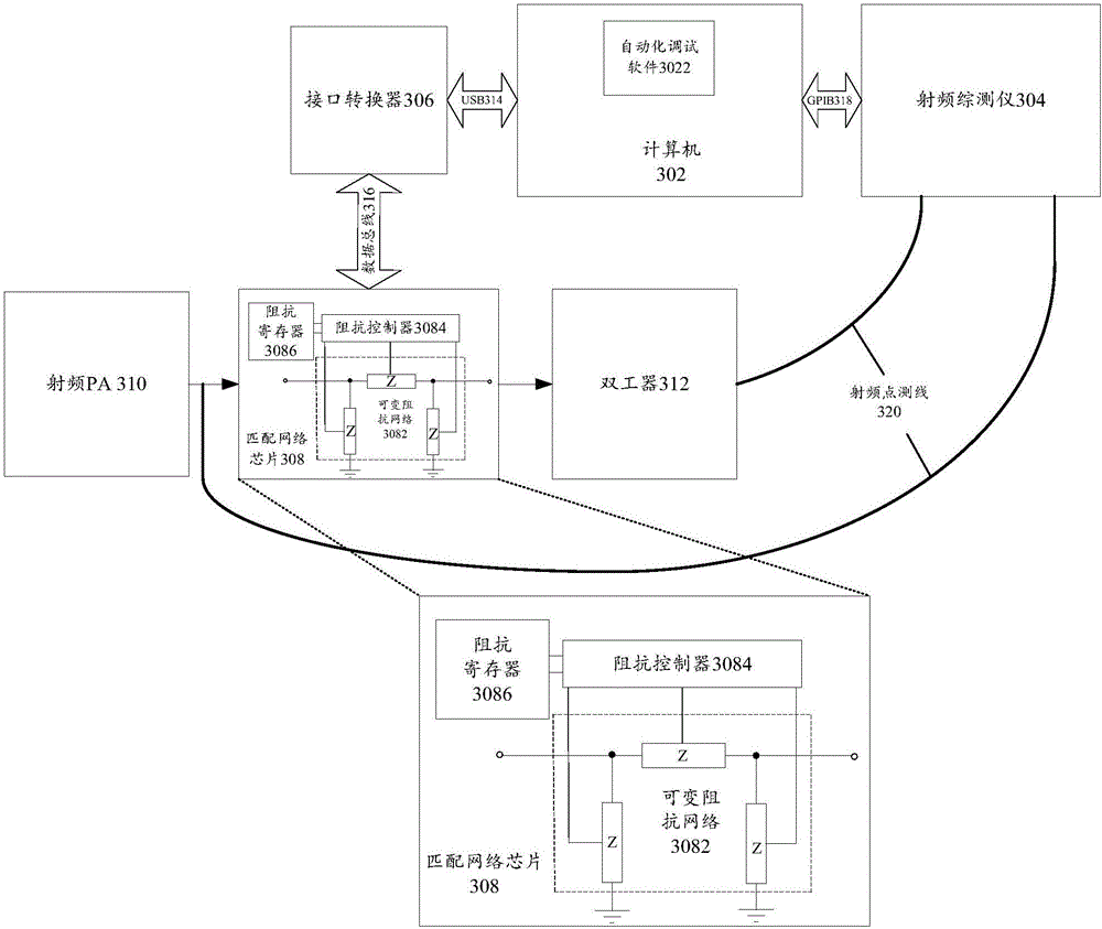

Image

  • Radio frequency matching system and method of realizing radio frequency matching automation
  • Radio frequency matching system and method of realizing radio frequency matching automation
  • Radio frequency matching system and method of realizing radio frequency matching automation

Examples


Embodiment Construction

[0034] In order to understand the above-mentioned purpose, features and advantages of the present invention more clearly, the present invention will be further described in detail below in conjunction with the accompanying drawings and specific embodiments.

[0035] In the following description, many specific details are set forth in order to fully understand the present invention, however, the present invention can also be implemented in other ways different from those described here, therefore, the present invention is not limited to the specific embodiments disclosed below limit.

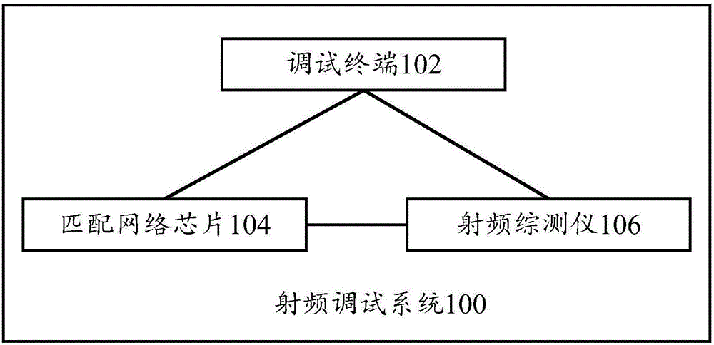
[0036] figure 1 A block diagram of a radio frequency matching system 100 according to an embodiment of the first aspect of the present invention is shown.

[0037] Such as figure 1 As shown, according to the first embodiment of the present invention, a radio frequency matching system 100 is provided, including: a debugging terminal 102 equipped with debugging software, and the debugging termina...


PUM


Abstract

The invention provides a radio frequency matching system and a method of realizing radio frequency matching automation. The radio frequency matching system comprises a debugging terminal, a radio-frequency integrated measuring instrument and a matched network chip, wherein the debugging terminal is installed with debugging software; the debugging terminal is connected to the radio-frequency integrated measuring instrument and the matched network chip respectively and is used for collecting a test result of the radio-frequency integrated measuring instrument and sending an impedance expectation value to the matched network chip; the debugging software is used for processing the test result and generating the impedance expectation value; one end of the radio-frequency integrated measuring instrument is connected to a radio frequency input source, and the other end is connected to a load output terminal, and the radio-frequency integrated measuring instrument establishes connection with the debugging terminal and is used for testing radio frequency pathway performance and acquiring the test result; and the matched network chip is arranged between the radio frequency input source and the load output terminal and is used for receiving the impedance expectation value, adjusting a self impedance according to the impedance expectation value and acquiring an optimum matching value. Through the technical scheme of the invention, based on calculating and an apparatus, radio frequency matching is automatically completed, and manual welding matching is replaced so that precision of radio frequency debugging is increased and a workload of a radio frequency engineer is reduced.

Description

technical field [0001] The invention relates to the technical field of radio frequency debugging, in particular to a radio frequency matching system and a method for realizing automatic radio frequency matching. Background technique [0002] With the development of smart phones, more and more frequency bands are supported by mobile phones. The RF channels of these frequency bands need to be debugged step by step by RF engineers. Only by finding the best RF matching can the RF indicators meet the actual use standards. In the process of realizing the present invention, the inventors found that in the prior art, with the continuous improvement of plate making and component technology, manual debugging becomes more and more difficult. And every time the matching is changed, manual welding is required, and then tested and verified. This process consumes a lot of engineering time, and the yield rate of manual soldering of such tiny devices is very low. [0003] Therefore, a new ...

Claims


Application Information

Patent Timeline
IPC IPC(8): H04B1/18H04L12/24H04L12/26H04L25/02
CPCH04B1/18H04L25/0278H04L41/0876H04L43/08H04L43/50
Inventor 葛厚洋
Owner YULONG COMPUTER TELECOMM SCI (SHENZHEN) CO LTD
Learn More