Electrode leads for use with implantable neuromuscular electrical stimulator

A neuromuscular and electrical stimulation technology, applied in the direction of implanting stimulators, spinal nerve electrodes, electrodes, etc., can solve problems such as lead displacement

Pending Publication Date: 2017-04-19
MAINSTAY MEDICAL
View PDF13 Cites 9 Cited by
  • Summary
  • Abstract
  • Description
  • Claims
  • Application Information

AI Technical Summary

Problems solved by technology

These currently known anchoring systems are not suitable for use in neuromuscular stimulation a

Method used


Image

  • Electrode leads for use with implantable neuromuscular electrical stimulator
  • Electrode leads for use with implantable neuromuscular electrical stimulator
  • Electrode leads for use with implantable neuromuscular electrical stimulator

Examples


Embodiment Construction

[0028]The neuromuscular stimulation lead of the present invention includes a lead body having a strain relief portion and a plurality of electrodes configured to provide electrical stimulation from an implantable pulse generator to neuromuscular tissue located in the patient's back. The leads disclosed herein are particularly useful for stimulating tissues associated with the lumbar spine for the restoration of muscle function and lumbar spine stability while overcoming the problems of lead migration and fatigue fracture observed with currently known electrode lead designs.

[0029] Stimulation leads with strain relief

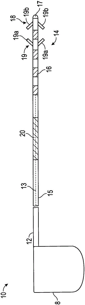
[0030] refer to figure 1 , depicts an exemplary stimulation lead 10 constructed in accordance with the principles of the present invention. Stimulation lead 10 includes proximal end 12 , a plurality of inner conductors 13 , distal region 14 , insulating sheath 15 , electrodes 16 , anchoring mechanism 18 including fixation elements 19 a and 19 b , and strain r...


PUM


Abstract

An apparatus for neuromuscular electrical stimulation is provided. The apparatus may be a stimulation lead having an elongated member made up of at least one conductor and an insulative sheath surrounding at least a portion of the conductor. A distal portion of the elongated member may include one or more electrodes and at least one fixation element to secure the one or more electrodes in or adjacent to a desired anatomical site for providing stimulation thereto. The stimulation lead has a strain relief portion on the proximal side of the one or more electrodes, configured to reduce axial forces on the distal region of the elongated member, and the effects thereof, to reduce the risk of, or even prevent, displacement of the one or more electrodes and to accommodate localized flexural motion. The apparatus also may include at least one fixation element sized and configured to be deployed between muscle layers to maintain the electrode position at the stimulation site.

Description

technical field [0001] The present application generally relates to a device for providing a lead for neuromuscular stimulation configured to limit axial force and tensile loading on the distal end of the lead and reduce motion of a stimulating electrode. Background technique [0002] Many medical devices contain elongated or tubular elements that need to be positioned at specific anatomical sites. Such devices include pacemakers, spinal and peripheral nerve stimulators for paresthesia systems and functional electrical stimulation, and drug delivery catheters. [0003] In the case of a pacemaker, for example, a lead wire may be threaded into a vein and then the lead wire anchored by use of a fixation element at the distal tip of the lead wire to reduce the risk of or even prevent displacement. Such fixation elements may be tines, fins or screws fixed in the trabeculae or musculature of the ventricles, atria or vessels of the heart. [0004] The sacral nerve stimulator lead...

Claims


Application Information

Patent Timeline
IPC IPC(8): A61N1/05A61N1/18A61N1/36
CPCA61N1/05A61N1/0504A61N1/0558A61N1/18A61N1/3605
Inventor J·A·史诺夫J·J·斯库比茨P·B·拉瓦特
Owner MAINSTAY MEDICAL
Why Eureka
Try Eureka