Eureka AIR delivers breakthrough ideas for toughest innovation challenges, trusted by R&D personnel around the world.

Terminal mounting structure for vehicle motor drive device

A technology of driving device and installation structure, which is applied in electromechanical devices, electric vehicles, vehicle energy storage, etc., can solve the problems of not clearly revealing power wiring, unclear power wiring, etc.

Active Publication Date: 2017-04-19
NTN CORP
View PDF7 Cites 1 Cited by
  • Summary
  • Abstract
  • Description
  • Claims
  • Application Information

AI Technical Summary

Problems solved by technology

[0003] However, the internal power wiring of the vehicle motor drive device disclosed in the vehicle motor drive device of Patent Document 1 is unclear.
In particular, Patent Document 1 does not clearly disclose the power wiring from the tip end of the cable leading out to the vehicle motor drive device to the stator coil of the motor part of the vehicle motor drive device.

Method used


Image

  • Terminal mounting structure for vehicle motor drive device
  • Terminal mounting structure for vehicle motor drive device
  • Terminal mounting structure for vehicle motor drive device

Examples


Embodiment Construction

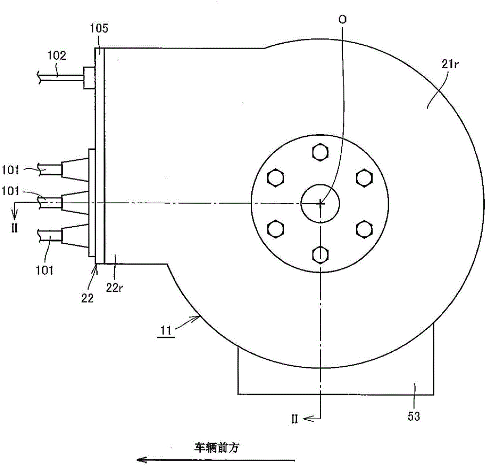
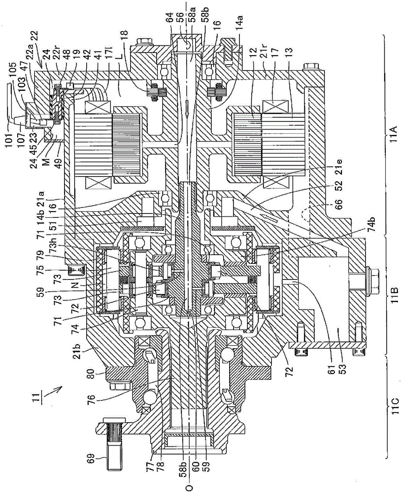
[0046] Embodiments of the present invention will be described in detail below with reference to the drawings. figure 1 It is a rear view showing the motor drive device for a vehicle having the terminal mounting structure of the present invention, and shows a state viewed from the inner side (inner panel side) in the vehicle width direction of the electric vehicle. figure 2 so figure 1 II-II in the figure is a cross section, which is a vertical cross-sectional view showing a state in which the motor drive device for a vehicle is viewed from the direction of the arrow. First, a motor drive device for a vehicle will be described. figure 1 with figure 2 The shown in-wheel motor drive device 11 is a vehicle motor drive device provided inside a wheel of an electric vehicle or a hybrid vehicle, and is attached to a vehicle body via a suspension device not shown.

[0047] Such as figure 1 As shown, the in-wheel motor driving device 11 has a substantially cylindrical shape, such ...


PUM


Abstract

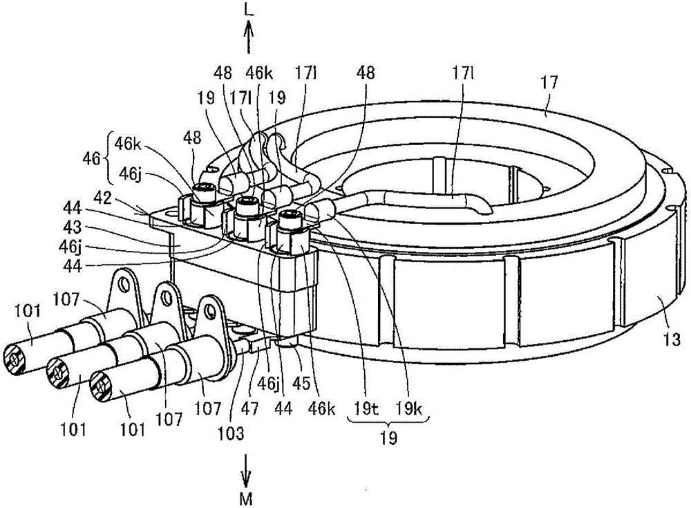
This terminal mounting structure is provided with: a plurality of recipient-side terminals (19) extending from respective distal ends of electrical leads (171); a mount (42) having an electrically insulating base material (43) and a plurality of supply-side conductive bars (44) that are disposed at an interval from one another and extend through the base material; a plurality of screws (48) that are screwed into screw holes formed in ends of the supply-side conductive bars through the recipient-side terminals in a direction intersecting with the direction of extension of the recipient-side terminals, thus fixedly contacting each of the recipient-side terminals to the respective corresponding supply-side conductive bars; and a contact prevention mechanism (46) that is provided to the mount and prevents contact between adjacent recipient-side terminals.

Description

technical field [0001] The present invention relates to a motor drive device for a vehicle that drives wheels of an electric vehicle or a hybrid vehicle, and more particularly to a structure in which a terminal of a motor coil is attached to a conductive rod on the power supply side inside the motor drive device for a vehicle. Background technique [0002] As an in-wheel motor drive device arranged in the road wheel internal space region of the wheel, or as an on-vehicle motor drive device mounted on the vehicle body and drives the wheel through a drive shaft, in the prior art, for example, JP 2010-2010 is known. 172069 Publication (Patent Document 1) discloses a motor drive device for a vehicle. A motor drive device for a vehicle, such as an in-wheel motor drive device or an on-vehicle motor drive device, is connected to a cable extending from the outside of the vehicle motor drive device, and receives electric power supplied through the cable. [0003] However, the intern...

Claims


Application Information

Patent Timeline
IPC IPC(8): H02K5/22H01R4/34H01R9/18
CPCB60L50/51H01R4/34H01R9/18H01R9/24H01R2201/26H02K5/22Y02T10/70H01R4/70H02K5/225
Inventor 田村四郎石川贵则太向真也
Owner NTN CORP
Why Eureka
Eureka Blog
Learn More