

Continuous feeding and spraying device
A spraying device and continuous technology, applied in the field of continuous feeding spraying devices, can solve the problems of uneven concentration, complex structure, inconvenience, etc., and achieve the effects of saving energy, improving efficiency and simplifying the structure of the device
- Summary
- Abstract
- Description
- Claims
- Application Information
AI Technical Summary
Problems solved by technology
Method used
Image

Examples
Embodiment 1
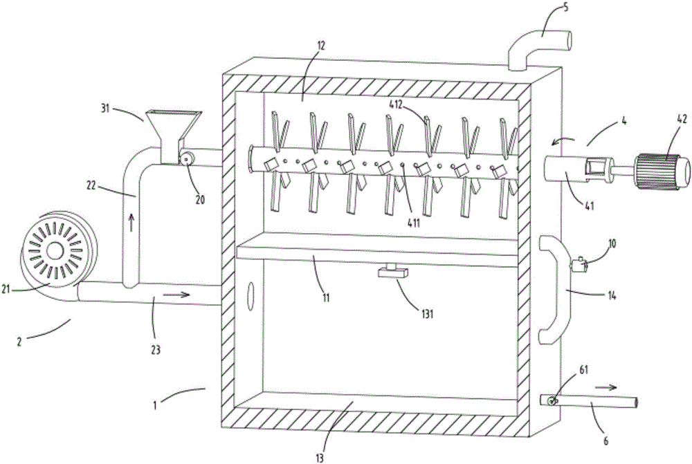
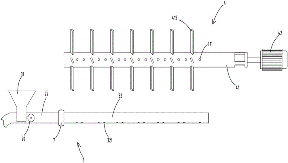
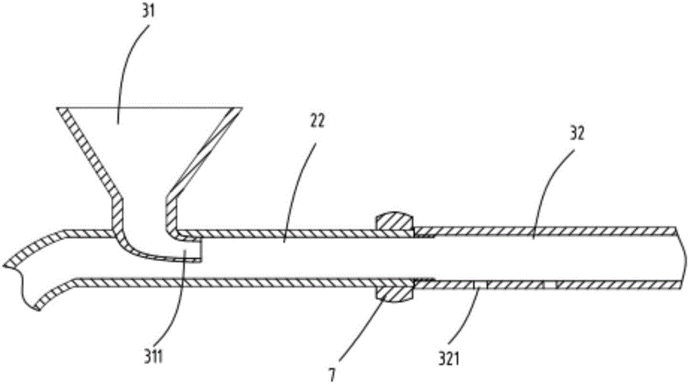
[0038] figure 1 It is a cut-away schematic diagram of a continuous feed spraying device, figure 2 It is a schematic diagram of the disassembly of the powder supply part and the stirring part, image 3 It is a schematic diagram of the structure of the powder warehouse, Figure 4 It is the overall schematic diagram of the continuous feeding spraying device. Such as figure 1 , figure 2 , image 3 , Figure 4 As shown, what is provided in this embodiment is a continuous feed spraying device, comprising a box body 1, which is divided into a mixing chamber 12 and a spraying chamber 13 up and down by a partition plate 11; the mixing chamber 12 and A pipeline 14 is connected between the spray chambers 13; a valve a10 is arranged in the pipeline 14;
[0039] Air blowing device 2, this device comprises blowing device 21, the inlet pipe a22 that extends out by blowing device 21 and the inlet pipe b23; Described inlet pipe a22 communicates with mixing chamber 12; Described inlet ...
Embodiment 2
[0054] Such as figure 1 , figure 2 , image 3 , Figure 4 As shown, the components that are the same as or corresponding to those in the first embodiment are marked with the corresponding reference numerals in the first embodiment. For the sake of simplicity, only the differences from the first embodiment will be described below. The difference between the second embodiment and the first embodiment is that: the spray chamber 13 is provided with a pressure monitoring device 131 for monitoring the air pressure in the spray chamber 13; the spray pipe 6 is provided with a valve c61; The above-mentioned valve c61 is connected with the signal of the pressure monitoring device 131; the switch operation of the spray pipe 6 is controlled by the pressure monitoring signal, and the valve c61 is opened only when the pressure reaches a certain level, so as to ensure that the power of spraying is sufficient and the effect of spraying is better; The valve a10, the valve b20 and the valve...
PUM
| Property | Measurement | Unit |
|---|---|---|
| Aperture | aaaaa | aaaaa |
Abstract
Description
Claims
Application Information