
Hotpot cooker with lifting structure

A lifting structure, hot pot technology, applied in the field of hot pot pots and pans, can solve the problems of sticking the pot, the ingredients are easily boiled, affecting the taste of the ingredients, etc., and achieve the effects of avoiding the loss of nutrients, safe eating process, and good cooking time

Inactive Publication Date: 2017-04-26
倪东海
View PDF5 Cites 7 Cited by
  • Summary
  • Abstract
  • Description
  • Claims
  • Application Information

AI Technical Summary

Problems solved by technology

[0004] (1) When cooking ingredients, if too many ingredients are put in and not eaten in time, the ingredients will directly contact the bottom of the pot. Over time, the ingredients will be easily boiled, and it will easily cause the pot to burn, thus destroying the hot pot The taste of the soup and the taste of the ingredients
[0005] (2) Since the hot pot soup is an opaque liquid, the ingredients in the soup are not easy to see during the boiling process, so users often need to use tools such as chopsticks and spoons to search for ingredients in the pot, which brings great inconvenience to the user. big inconvenience
[0006] In addition, the existing hot pot pot is only used as a container, which itself does not have a heating function, and it needs to cooperate with heating equipment such as an induction cooker to enjoy hot pot delicacies; therefore, its structure needs to be further improved

Method used


Image

  • Hotpot cooker with lifting structure
  • Hotpot cooker with lifting structure
  • Hotpot cooker with lifting structure

Examples


Embodiment Construction

[0031] The present invention will be further described in detail below in conjunction with the embodiments of the drawings.

[0032] Such as Figure 1 to Figure 5 The embodiment shown,

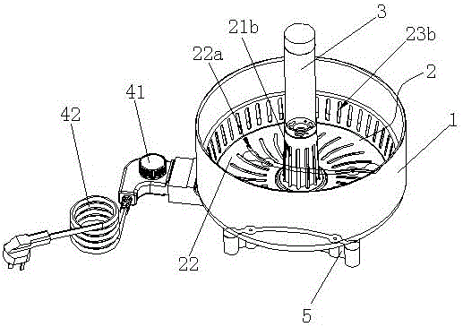
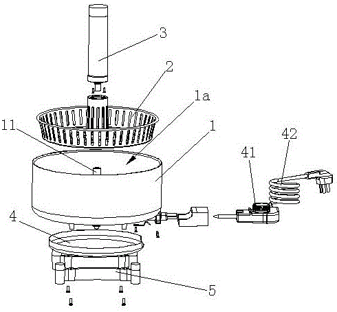
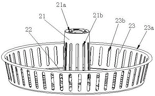
[0033] Description of icon numbers: outer pot body 1, hot pot cavity 1a, central column 11, inner pot body 2, central body 21, fixed hole 21a, third soup drain hole 21b, bottom surface 22, first soup drain hole 22a, rib 23 , Flange 23a, second leakage hole 23b, lifter 3, cover 3a, charging port 3b, lifter housing 31, battery 32, circuit board 33, motor 34, reducer 35, connecting rod 36, nut 36a, Screw 37, guide post 38, upper fixing base 39a, lower fixing base 39b, heating plate 4, temperature controller 41, power cord 42, base 5.

[0034] Such as Figure 1 to Figure 5 As shown,

[0035] A hot pot pot with a lifting structure, comprising an outer pot body 1, a hot pot cavity 1a is arranged in the outer pot body 1, and an inner pot body 2 is arranged in the hot pot cavity 1a, the inner pot body 2 an...


PUM


Abstract

The invention discloses a hotpot cooker with a lifting structure. The hotpot cooker with the lifting structure is characterized in that a hotpot cavity is arranged in an outer cooker body, an inner cooker body is arranged in the hotpot cavity, a lifter is arranged in the centers of the inner cooker body and the outer cooker body vertically fittingly and comprises a lifter shell as well as a battery, a circuit board, a motor, a speed reducer, a connecting rod and a screw which are arranged in the lifter shell, an output shaft of the motor matches with the screw through the speed reducer, the lower end of the connecting rod is fixed on a central post of the outer cooker body, a nut is connected to the upper end of the connecting rod and is in screw joint with the screw, a guide post is arranged in the lifter shell and passes through the nut to be fixed in the lifter shell, the inner cooker body is fixed to the lifter shell, the circuit board is in signal connection with a lifting controller, and a heating disc is arranged at the bottom of the outer cooker body and is connected with a power line with a temperature controller. The hotpot cooker with the lifting structure has the advantages of simple structure, convenience in operation, a self-heating function and capability of better controlling food material cooking time.

Description

Technical field [0001] The invention relates to the technical field of cooking utensils, in particular to a hot pot pot with a lifting structure. Background technique [0002] Generally speaking, hot pot is a cooking method that uses a pot as an appliance, uses a heat source to boil the pot, boils water or soup, and cooks food; its ingredients are diverse, and they are eaten hot and are widely welcomed, especially in winter. It is favored by people. [0003] However, the existing hot pot pots have the following disadvantages in the cooking process: [0004] (1) When cooking ingredients, if you put too much ingredients and not eaten them in time, the ingredients will directly contact the bottom of the pot. Over time, the ingredients will be easy to boil, and it will easily cause the pot to become sticky and damage the hot pot. The taste of the soup and the taste of the ingredients are affected. [0005] (2) Since the hot pot soup is an opaque liquid, the ingredients in the soup are n...

Claims


Application Information

Patent Timeline
IPC IPC(8): A47J27/00A47J36/20
CPCA47J27/004A47J36/20
Inventor 倪东海
Owner 倪东海
Learn More